


- 20 -
Hardware Installation
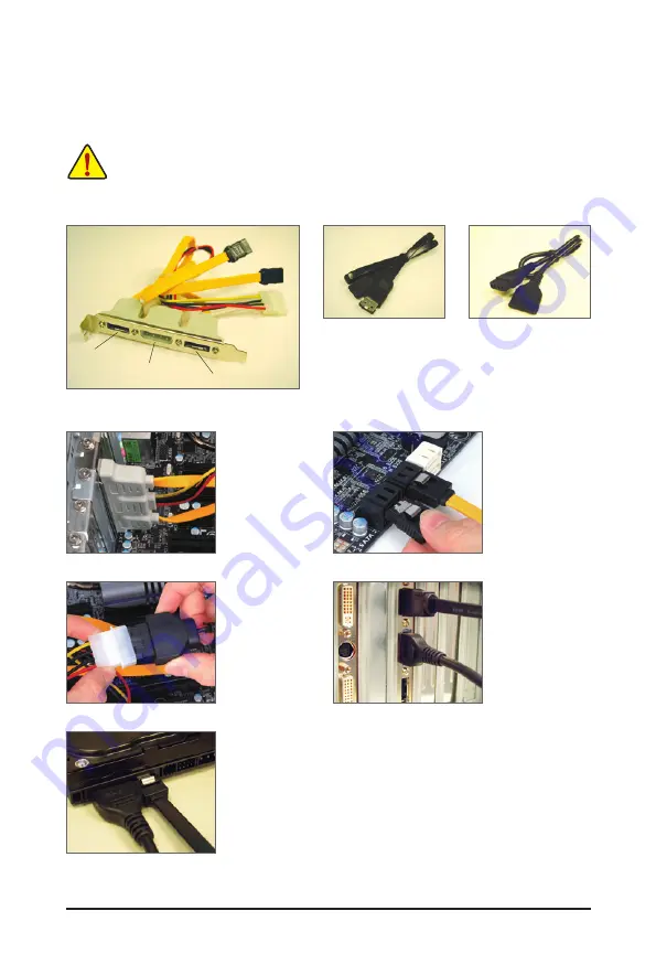
1-7 Installing the SATA Bracket
•
Turn off your system and the power switch on the power supply before installing or removing the
SATA bracket and SATA power cable to prevent damage to hardware.
•
Insert the SATA signal cable and SATA power cable securely into the corresponding connectors
when installing.
The SATA bracket
allows you to connect external SATA device(s) to your system by expanding the internal
SATA port(s) to the chassis back panel.
Follow the steps below to install the SATA bracket:
The SATA bracket includes one SATA bracket, one
SATA signal cable, and one SATA power cable.
Step 1:
Locate one free PCI
slot and secure the
SATA bracket to the
chassis back panel
with a screw.
Step 2:
Connect the SATA ca-
ble from the bracket
to the SATA port on
your motherboard.
Step 3:
Connect the power
c a b l e f r o m t h e
bracket to the power
supply.
Step 4:
Plug one end of the
SATA signal cable
into the external SATA
connector on the
bracket. Then attach
the SATA power cable
to the power connec-
tor on the bracket.
Step 5:
Connect the other ends of the SATA signal cable and SATA power cable to
your SATA device. For SATA device in external enclosure, you only need to
connect the SATA signal cable. Before connecting the SATA signal cable,
make sure to turn off the power of the external enclosure.
External SATA Connector
Power Connector
External SATA
Connector
SATA Bracket
SATA Signal Cable
SATA Power Cable
Summary of Contents for GA-P67A-UD7
Page 2: ...Motherboard GA P67A UD7 Nov 8 2010 Nov 8 2010 Motherboard GA P67A UD7...
Page 34: ...34 Hardware Installation...
Page 62: ...BIOS Setup 62...
Page 86: ...Unique Features 86...
Page 123: ...123 Appendix...
Page 124: ...Appendix 124...
Page 125: ...125 Appendix...
Page 126: ...Appendix 126...


