background image

- 19 -

2-2 M.I.T.

Whether the system will work stably with the overclock/overvoltage settings you made is dependent on your overall 

system configurations. Incorrectly doing overclock/overvoltage may result in damage to CPU, chipset, or memory 

and reduce the useful life of these components. This page is for advanced users only and we recommend you not to 

alter the default settings to prevent system instability or other unexpected results. (Inadequately altering the settings 

may result in system's failure to boot. If this occurs, clear the CMOS values and reset the board to default values.)

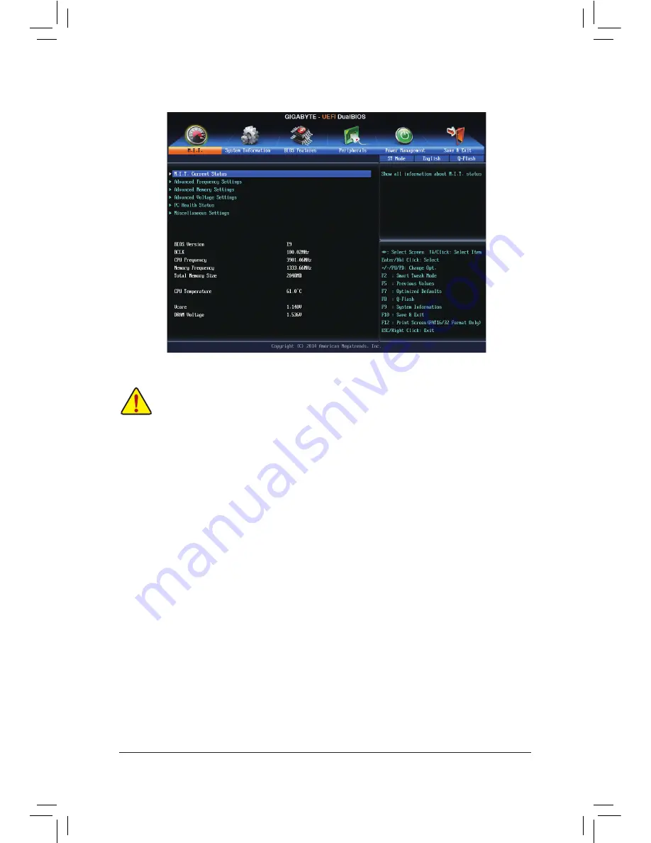
This section provides information on the BIOS version, CPU base clock, CPU frequency, memory frequency, 

total memory size, CPU temperature, Vcore, and memory voltage.


`

M.I.T. Current Status


This screen provides information on CPU/memory frequencies/parameters.


&

Processor Graphics Clock


Allows you to set the onboard graphics clock. The adjustable range is from 400 MHz to 4000 MHz. (Default: 

Auto)


&

CPU Upgrade

 (Note)


Allows you to set the CPU frequency. Options may vary depending on the CPU being used. (Default: Auto)


&

CPU Clock Ratio


Allows you to alter the clock ratio for the installed CPU. The adjustable range is dependent on the CPU 

being installed.


&

CPU Frequency


Displays the current operating CPU frequency.


`

Advanced CPU Core Settings


&

CPU Clock Ratio, CPU Frequency


The settings above are synchronous to those under the same items on the 

Advanced Frequency Settings


menu.


&

K OC

 (Note)


Allows for increased performance by using certain CPUs. (Default: Auto)

(Note)  This item is present only when you install a CPU that supports this feature. For more information about 

Intel

®

 CPUs' unique features, please visit Intel's website.


`

Advanced Frequency Settings 

Summary of Contents for GA-H97M-Gaming 3

Page 1: ...GA H97M Gaming 3 User s Manual Rev 1001 12ME H97MG3 1001R...

Page 2: ...mitted or published in any form or by any means without GIGABYTE s prior written permission In order to assist in the use of this product carefully read the User s Manual For product related informati...

Page 3: ...PU 9 1 4 Installing the Memory 10 1 5 Installing an Expansion Card 10 1 6 Back Panel Connectors 10 1 7 Internal Connectors 12 Chapter 2 BIOS Setup 18 2 1 Startup Screen 18 2 2 M I T 19 2 3 System Info...

Page 4: ...sk 5 5 Two SATA cables 5 5 User s Manual 5 5 I O Shield GA H97M Gaming 3 Motherboard Layout F_USB30 KB_MS_USB3 CPU_FAN LGA1150 ATX AUDIO DDR3_4 DDR3_2 DDR3_3 DDR3_1 BAT ATX_12V Intel H97 CLR_CMOS M_BI...

Page 5: ...00 MHz 1 PCI Express x16 COM LPT 8 USB 2 0 1 1 6 USB 3 0 2 0 DDR3 1600 1333 MHz PCI Express Bus PCI Express Bus 6 SATA 6Gb s HDMI DVI D D Sub DMI 2 0 FDI x16 LPC Bus x1 x1 1 PCI Express x1 Center Subw...

Page 6: ...ry If you do not have an ESD wrist strap keep your hands dry and first touch a metal object to eliminate static electricity Prior to installing the motherboard please have it on top of an antistatic p...

Page 7: ...4096x2160 24Hz or 2560x1600 60Hz Support for HDMI 1 4a version 1 x DisplayPort supporting a maximum resolution of 4096x2160 24Hz or 3840x2160 60Hz Support for DisplayPort 1 2 version Support for up t...

Page 8: ...MI port 1 x DisplayPort 4 x USB 3 0 2 0 ports 4 x USB 2 0 1 1 ports 1 x RJ 45 port 6 x audio jacks Center Subwoofer Speaker Out Rear Speaker Out Side Speaker Out Line In Line Out Mic In I O Controller...

Page 9: ...re specifications including the CPU graphics card memory hard drive etc Unique Features ON OFF Charge Smart TimeLock Smart Recovery 2 System Information Viewer USB Blocker Support for Q Flash Support...

Page 10: ...we recommend that you install them in the DDR3_1 and DDR3_2 sockets 1 4 Installing the Memory Read the following guidelines before you begin to install the memory Make sure that the motherboard suppor...

Page 11: ...bi directional audio transmission DisplayPort can support both DPCP and HDCP content protection mechanisms You can use this port to connect your DisplayPort supported monitor The maximum supported res...

Page 12: ...nnect Before installing the devices be sure to turn off the devices and your computer Unplug the power cord from the power outlet to prevent damage to the devices After installing the device and befor...

Page 13: ...e the chassis ATX_12V 13 1 24 12 ATX ATX Pin No Definition Pin No Definition 1 3 3V 13 3 3V 2 3 3V 14 12V 3 GND 15 GND 4 5V 16 PS_ON soft On Off 5 GND 17 GND 6 5V 18 GND 7 GND 19 GND 8 Power Good 20 5...

Page 14: ...lugging for the SATAports refer to Chapter 2 BIOS Setup Peripherals SATAConfiguration for more information 6 F_PANEL Front Panel Header Connect the power switch reset switch speaker chassis intrusion...

Page 15: ...t Header This header supports digital S PDIF Out and connects a S PDIF digital audio cable provided by expansion cards for digital audio output from your motherboard to certain expansion cards like gr...

Page 16: ...acket be sure to turn off your computer and unplug the power cord from the power outlet to prevent damage to the USB bracket 11 COM Serial Port Header The COM header can provide one serial port via an...

Page 17: ...values may not be accurate or may be lost You may clear the CMOS values by removing the battery 1 Turn off your computer and unplug the power cord 2 Gently remove the battery from the battery holder...

Page 18: ...s you need to to prevent system instability or other unexpected results Inadequately altering the settings may result in system s failure to boot If this occurs try to clear the CMOS values and reset...

Page 19: ...nt Status This screen provides information on CPU memory frequencies parameters Processor Graphics Clock Allows you to set the onboard graphics clock The adjustable range is from 400 MHz to 4000 MHz D...

Page 20: ...o select the number of CPU cores to enable in an Intel multi core CPU the number of CPU cores may vary by CPU Auto lets the BIOS automatically configure this setting Default Auto Hyper Threading Techn...

Page 21: ...onous to those under the same items on the Advanced Frequency Settings menu Memory Boot Mode Provides memory detection and training methods Auto Lets the BIOS automatically configure this setting Defa...

Page 22: ...fferent speeds according to the CPU temperature You can adjust the fan speed with EasyTune based on your system requirements Default Silent Allows the fan to run at slow speeds Manual Allows you to co...

Page 23: ...peed control function and adjust the fan speed Normal Allows the fan to run at different speeds according to the system temperature You can adjust the fan speed with EasyTune based on your system requ...

Page 24: ...nd use the Page Up or Page Down key to set the desired value System Time Sets the system time The time format is hour minute and second For example 1 p m is 13 0 0 Use Enter to switch between the Hour...

Page 25: ...a password is required every time the system boots or only when you enter BIOS Setup After configuring this item set the password s under the Administrator Password User Password item Setup A passwor...

Page 26: ...tem to Enabled for legacy operating system such as Windows NT4 0 Default Disabled Execute Disable Bit Note Enables or disables Intel Execute Disable Bit function This function may enhance protection f...

Page 27: ...e only when CSM Support is set to Always Network stack Disables or enables booting from the network to install a GPT format OS such as installing the OS from the Windows Deployment Services server Def...

Page 28: ...ed mode when BIOS has xHCI pre boot support Default Auto BIOS routes the sharable ports to EHCI controller Then it uses ACPI protocols to provide an option to enable the xHCI controller and reroute th...

Page 29: ...to Enabled to ensure proper device functionality when chaining two KVM switches Default Disabled OnBoard LAN Controller Enables or disables the onboard LAN function Default Enabled If you wish to inst...

Page 30: ...e Extended Capabilities Port EPP Mode ECP Mode This item is configurable only when Parallel Port is set to Enabled Intel R Smart Connect Technology ISCT Support Enables or disables Intel Smart Connect...

Page 31: ...ower On Password Set the password when Power On By Keyboard is set to Password Press Enter on this item and set a password with up to 5 characters and then press Enter to accept To turn on the system...

Page 32: ...Press Enter on the device you select and select Yes to confirm Your system will restart automatically and boot from that device Save Profiles This function allows you to save the current BIOS settings...

Page 33: ...uration make sure Integrated SATA Controller is enabled To create RAID set SATA Mode Selection to RAID If you do not want to create RAID set this item to IDE or AHCI 2 If you want to configure UEFI RA...

Page 34: ...ry The stripe block size can be set from 4 KB to 128 KB Once you have selected the stripe block size press Enter 5 Enter the array capacity and press Enter Finally press Enter on the Create Volume ite...

Page 35: ...top right corner of the screen and select Run Run exe Or go to My Computer double click the optical drive and execute the Run exe program 3 2 Drivers Installation Xpress Install will automatically sc...

Page 36: ...eatment collection recycling and disposal of electric and electronic devices and their components Under the Directive used equipment must be marked collected separately and disposed of properly WEEE S...

Page 37: ...ore of the following measures Reorient or relocate the receiving antenna Increase the separation between the equipment and receiver Connect the equipment into an outlet on a circuit different from tha...

Page 38: ...38...

Page 39: ...39...

Page 40: ...ggts gigabyte com tw WEB address English http www gigabyte com WEB address Chinese http www gigabyte tw You may go to the GIGABYTE website select your language in the language list on the top right co...

Reviews: