


- 33 -
BIOS Setup
2-2
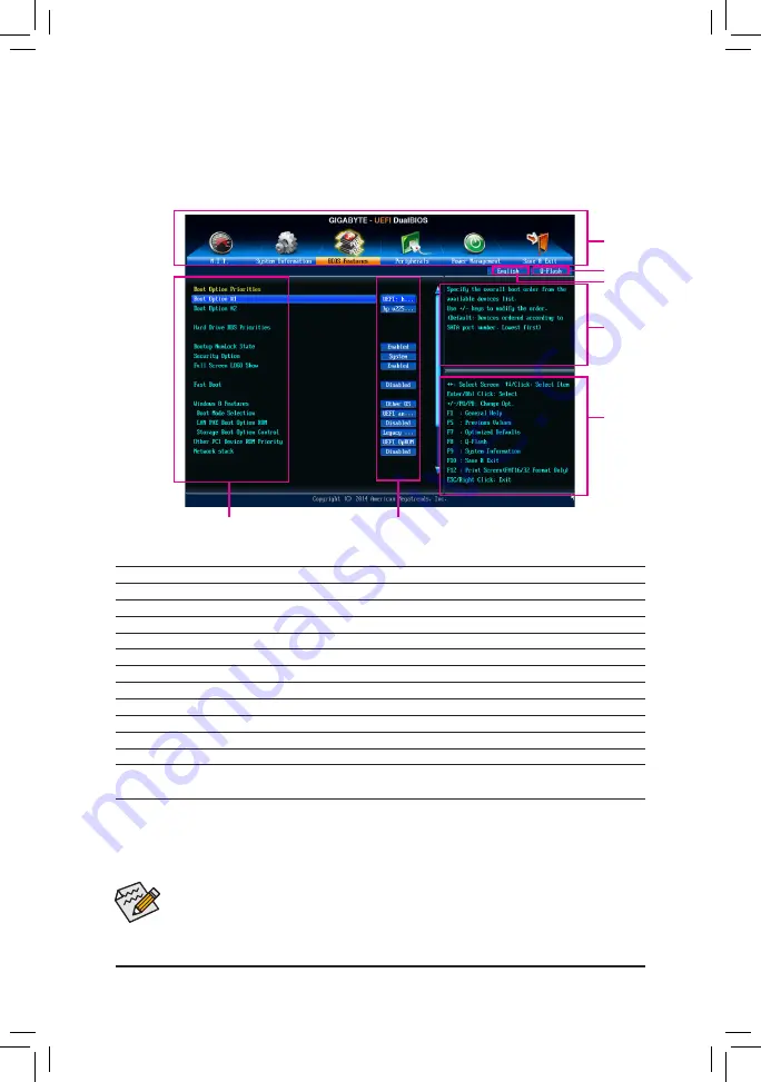
The Main Menu
On the main menu of the BIOS Setup program, press arrow keys to move among the items and press <Enter>
to accept or enter a sub-menu. Or you can use your mouse to select the item you want.
(Sample BIOS Version: F1a)
Setup Menus
Function Keys
Help
Enter Q-Flash
Coniguration Items
Current Settings
Select Default
Language
BIOS Setup Program Function Keys
<
f
><
g
>
Move the selection bar to select a setup menu
<
h
><
i
>
Move the selection bar to select an coniguration item on a menu
<Enter>
Execute command or enter a menu
<+>/<Page Up>
Increase the numeric value or make changes
<->/<Page Down>
Decrease the numeric value or make changes
<F1>
Show descriptions of the function keys
<F5>
Restore the previous BIOS settings for the current submenus
<F7>
Load the Optimized BIOS default settings for the current submenus
<F8>
Access the Q-Flash utility
<F9>
Display system information
<F10>
Save all the changes and exit the BIOS Setup program
<F12>
Capture the current screen as an image and save it to your USB drive
<Esc>
Main Menu: Exit the BIOS Setup program
Submenus: Exit current submenu
•
When the system is not stable as usual, select the
Load Optimized Defaults
item to set your
system to its defaults.
•
The BIOS Setup menus described in this chapter are for reference only and may differ by BIOS
version.
Summary of Contents for GA-F2A88X-D3HP
Page 2: ...Motherboard GA F2A88X D3HP Nov 27 2015 Nov 27 2015 Motherboard GA F2A88X D3HP...
Page 8: ...8...
Page 30: ...30 Hardware Installation...
Page 64: ...Coniguring a RAID Set 64...
Page 80: ...Unique Features 80...
Page 92: ...Appendix 92...
Page 93: ...93 Appendix...
Page 94: ...Appendix 94...


