background image

Hardware Installation

- 13 -

1-3

Installing the CPU and CPU Cooler

Read the following guidelines before you begin to install the CPU:

Make sure that the motherboard supports the CPU.
(Go to GIGABYTE's website for the latest CPU support list.)

Always turn off the computer and unplug the power cord from the power outlet before
installing the CPU to prevent hardware damage.

Locate the pin one of the CPU. The CPU cannot be inserted if oriented incorrectly. (Or you
may locate the notches on both sides of the CPU and alignment keys on the CPU socket.)

Apply an even and thin layer of thermal grease on the surface of the CPU.

Do not turn on the computer if the CPU cooler is not installed, otherwise overheating and
damage of the CPU may occur.

Set the CPU host frequency in accordance with the CPU specifications. It is not recom-
mended that the system bus frequency be set beyond hardware specifications since it
does not meet the standard requirements for the peripherals. If you wish to set the frequency
beyond the standard specifications, please do so according to your hardware specifications
including the CPU, graphics card, memory, hard drive, etc.

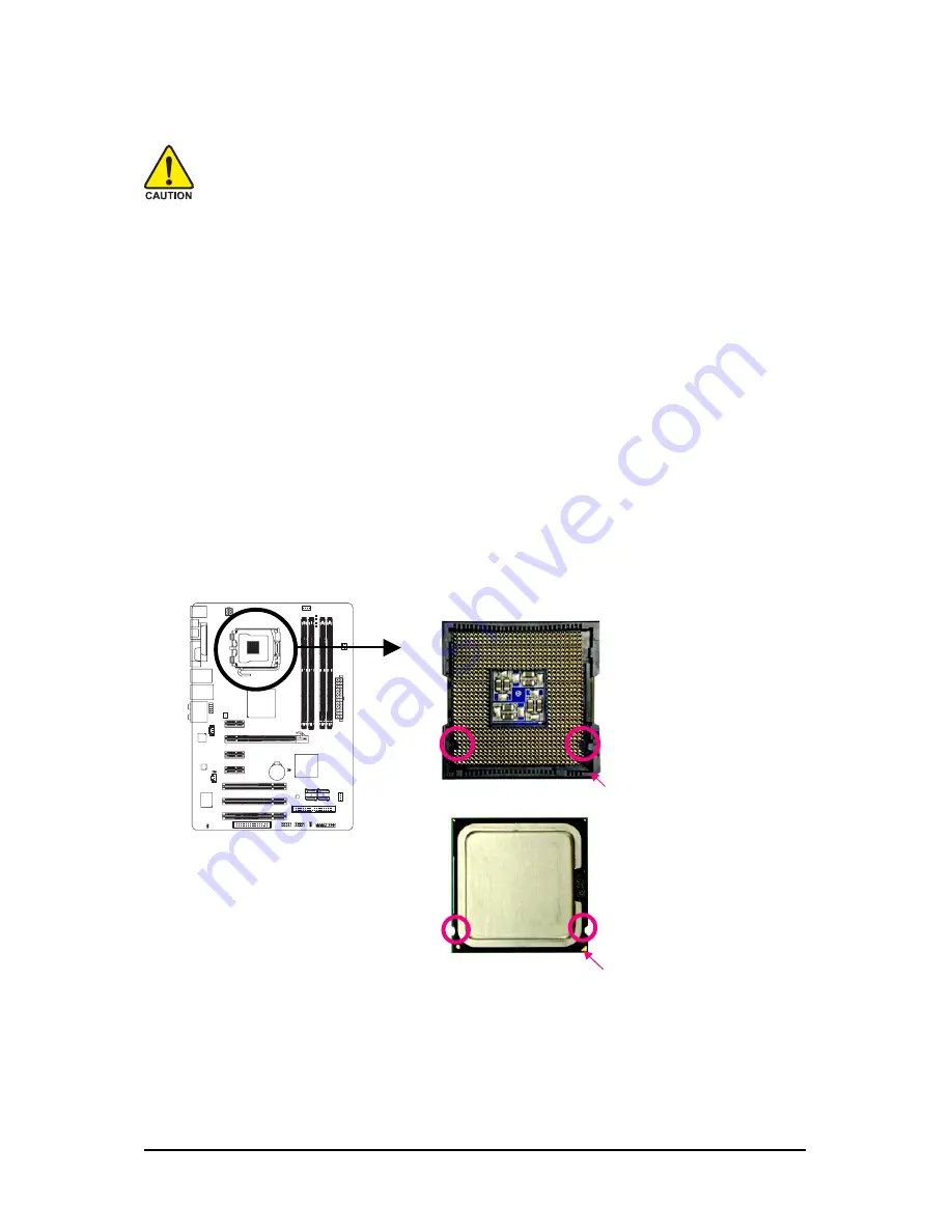
1-3-1 Installing the CPU

A. Locate the alignment keys on the motherboard CPU socket and the notches on the CPU.

Notch

Notch

Alignment Key

Alignment Key

LGA 775 CPU

LGA775 CPU Socket

Pin One Corner of the CPU Socket

Triangle Pin One Marking on the CPU

Summary of Contents for GA-EP31-DS3L

Page 1: ...GA EP31 DS3L LGA775 socket motherboard for Intel CoreTM processor family Intel Pentium processor family Intel Celeron processor family User s Manual Rev 1002 12ME EP31DS3L 1002R...

Page 2: ...Mar 12 2008 Motherboard GA EP31 DS3L Motherboard GA EP31 DS3L Mar 12 2008...

Page 3: ...form or by any means without GIGABYTE s prior written permission Documentation Classifications Inordertoassistintheuseofthisproduct GIGABYTEprovidesthefollowingtypesofdocumentations For quick set up o...

Page 4: ...figuration 16 1 4 2 Installing a Memory 17 1 5 Installing an Expansion Card 18 1 6 Back Panel Connectors 19 1 7 InternalConnectors 21 Chapter 2 BIOS Setup 31 2 1 StartupScreen 32 2 2 The Main Menu 33...

Page 5: ...h Utility 62 4 2 2 Updating the BIOS with the BIOS Utility 65 4 3 EasyTune 5 Pro 67 4 4 Dynamic Energy Saver 68 4 5 Windows Vista ReadyBoost 70 Chapter 5 Appendix 71 5 1 ConfiguringAudioInputandOutput...

Page 6: ...I O Shield Optional Items 2 port USB 2 0 bracket Part No 12CR1 1UB030 51R S PDIF in cable Part No 12CR1 1SPDIN 01R 2 port SATA power cable Part No 12CF1 2SERPW 01R The box contents above are for refer...

Page 7: ...IO BIOS PCIE_16 PCIE_3 F_USB2 IDE1 PCIE_1 SPDIF_I CI DDRII1 DDRII2 DDRII3 DDRII4 BAT F_PANEL IT8718 SATAII0 ATX_12V Intel P31 Intel ICH7 PWR_LED FDD PCIE_2 SATAII1 PCI1 PCI2 PCI3 USB CLR_CMOS LPT CODE...

Page 8: ...CLK 33 MHz PCIe CLK 100 MHz PCI Express x16 IT8718 Floppy PS 2 KB Mouse LPT Port CPU CLK 333 266 200 MHz Center Subwoofer Speaker Out Line Out MIC Line In SPDIF In SPDIF Out Side Speaker Out Surround...

Page 9: ...s dry and first touch a metal object to eliminate static electricity Prior to installing the motherboard please have it on top of an antistatic pad or within an electrostaticshieldingcontainer Beforeu...

Page 10: ...4 GB of system memory Note 1 Dual channel memory architecture Support for DDR2 1066 800 667 MHz memory modules Go to GIGABYTE s website for the latest memory support list Audio Realtek ALC888 codec Hi...

Page 11: ...header Back Panel 1 x PS 2 keyboard port Connectors 1 x PS 2 mouse port 1 x parallel port 1 x serial port 1 x coaxial S PDIF Out connector 1 x optical S PDIF Out connector 4 x USB 2 0 1 1 ports 1 x R...

Page 12: ...d on standard PC architecture a certain amount of memory is reserved for system usage and therefore the actual memory size is less than the stated amount For example 4 GB of memory size will instead b...

Page 13: ...surface of the CPU Do not turn on the computer if the CPU cooler is not installed otherwise overheating and damage of the CPU may occur Set the CPU host frequency in accordance with the CPU specificat...

Page 14: ...hes with the socket alignment keys and gently insert the CPU into position Step 3 Remove the protective socket cover from the load plate To protect the CPU socket always replace the protective socket...

Page 15: ...ll Step 3 Place the cooler atop the CPU aligning the four push pins through the pin holes on the motherboard Push down on the push pins diagonally Step 4 You should hear a click when pushing down each...

Page 16: ...de will double the original memory bandwidth The four DDR2 memory sockets are divided into two channels and each channel has two memory sockets as following Channel 0 DDRII1 DDRII2 Channel 1 DDRII3 DD...

Page 17: ...otch so it can only fit in one direction Follow the steps below to correctly install your memory modules in the memory sockets Step 1 Note the orientation of the memory module Spread the retaining cli...

Page 18: ...ard until it is fully seated in the slot 3 Make sure the metal contacts on the card are completely inserted into the slot 4 Secure the card s metal bracket to the chassis back panel with a screw 5 Aft...

Page 19: ...nector Serial Port Use the serial port to connect devices such as a mouse modem or other peripherals USB Port The USB port supports the USB 2 0 1 1 specification Use this port for USB devices such as...

Page 20: ...in devices such as an optical drive walkman etc Line Out Jack Green The default line out jack Use this audio jack for a headphone or 2 channel speaker This jack can be used to connect front speakers...

Page 21: ...to turn off the devices and your computer Unplug the power cord from the power outlet to prevent damage to the devices After installing the device and before turning on the computer make sure the dev...

Page 22: ...supply is turned off and all devices are properly installed The power connector possesses a foolproof design Connect the power supply cable to the power connector in the correct orientation The 12V po...

Page 23: ...sipation it is recommended that a system fan be installed inside the chassis 1 CPU_FAN PWR_FAN 1 SYS_FAN1 1 1 SYS_FAN2 7 FDD Floppy Disk Drive Connector This connector is used to connect a floppy disk...

Page 24: ...or example master or slave For information about configuring master slave settings for the IDE devices read the instructions from the device manufacturers 39 1 40 2 9 SATAII0 1 2 3 SATA 3Gb s Connecto...

Page 25: ...ven damage it Pin No Definition 1 MIC 2 GND 3 MIC Power 4 NC 5 Line Out R 6 NC 7 NC 8 No Pin 9 Line Out L 10 NC For AC 97FrontPanelAudio For HD Front Panel Audio 1 2 9 10 Pin No Definition 1 MIC2_L 2...

Page 26: ...different patterns to indicate the problem Refer to Chapter 5 Troubleshooting for information about beep codes HD IDE Hard Drive Activity LED Blue Connects to the hard drive activity LED on the chass...

Page 27: ...Pin No Definition 1 CD L 2 GND 3 GND 4 CD R 1 14 SPDIF_I S PDIF In Header Red This header supports digital S PDIF in and can connect to an audio device that supports digital audio out via an optional...

Page 28: ...HDMI display at the same time For information about connecting the S PDIF digital audio cable carefully read the manual for your expansion card 1 Pin No Definition 1 SPDIFO 2 GND 16 F_USB1 F_USB2 USB...

Page 29: ...es place a jumper cap on the two pins to temporarily short the two pins or use a metal object like a screwdriver to touch the two pins for a few seconds Open Normal Short Clear CMOS Values Always turn...

Page 30: ...r making them short for 5 seconds 3 Replace the battery 4 Plug in the power cord and restart your computer Always turn off your computer and unplug the power cord before replacing the battery Replace...

Page 31: ...upgrade or back up BIOS without entering the operating system BIOS is a Windows based utility that searches and downloads the latest version of BIOS from the Internet and updates the BIOS For instruc...

Page 32: ...s Recovery2 to back up hard drive data using the motherboard driver disk the F9 key can be used for subsequent access to XpressRecovery2 during the POST For more information refer to Chapter 4 Xpress...

Page 33: ...Help for each item is in the Item Help block on the right side of the submenu BIOS Setup Program Function Keys Move the selection bar to select an item Enter Execute command or enter the submenu Esc M...

Page 34: ...r Management Setup Use this menu to configure all the power saving functions PnP PCI Configurations Use this menu to configure the system s PCI PnP resources PC Health Status Use this menu to see info...

Page 35: ...Detection Press Enter to autodetect the parameters of the IDE SATA device on this channel IDE Channel 0 Master Slave Configure your IDE SATA devices by using one of the three methods below Auto Lets...

Page 36: ...standard floppy disk drive Options are Disabled default Drive A Halt on Allows you to determine whether the system will stop for an error during the POST No Errors The system boot will not stop for a...

Page 37: ...e list Press Esc to exit this menu when finished First Second Third Boot Device Specifies the boot order from the available devices Use the up or down arrow key to select a device and press Enter to a...

Page 38: ...verheated Default Enabled CPU EIST Function Note Enables or disables Enhanced Intel SpeedStep Technology EIST Depending on CPU loading Intel EIST technology can dynamically and effectively lower the C...

Page 39: ...A controller Disabled Disables the integrated SATA controller Auto Lets BIOS set SATA devices to Combined or Enhanced mode If your onboard SATA controller is automatically configured to Combined mode...

Page 40: ...g the onboard audio set this item to Disabled Onboard H W LAN Enables or disables the onboard LAN function Default Enabled If you wish to install a 3rd party add in network card instead of using the o...

Page 41: ...Length 1 6m Explanation A fault or short might occur at about 1 6m on Part 1 2 Note Part 4 5 and Part 7 8 are not used in a 10 100 Mbps environment so their Status fields will show Open and the length...

Page 42: ...t any time S3 STR Enables the system to enter the ACPI S3 Suspend to RAM sleep state default In S3 sleep state the system appears to be off and consumes less power than in the S1 state When signaled b...

Page 43: ...this function Default Double Click Double click on left button on the PS 2 mouse to turn on the system Power On By Keyboard Allows the system to be turned on by a PS 2 keyboard wake up event Note you...

Page 44: ...gns IRQ 3 4 5 7 9 10 11 12 14 15 to the second PCI slot PCI3 IRQ Assignment Auto BIOS auto assigns IRQ to the third PCI slot Default 3 4 5 7 9 10 11 12 14 15 Assigns IRQ 3 4 5 7 9 10 11 12 14 15 to th...

Page 45: ...status and the Case Opened field will show No at next boot Default Disabled Case Opened Displays the detection status of the chassis intrusion detection device attached to the motherboard CI header If...

Page 46: ...r disables the CPU fan speed control function Enabled allows the CPU fan to run at different speed according to the CPU temperature You can adjust the fan speed with EasyTune based on system requireme...

Page 47: ...hese components This page is for advanced users only and we recommend you not to alter the default settings to prevent system instability or other unexpected results Inadequately altering the settings...

Page 48: ...in accordance with the CPU specifications PCI Express Frequency Mhz Allows you to manually set the PCIe clock frequency The adjustable range is from 90 MHz to 150 MHz Auto sets the PCIe clock frequen...

Page 49: ...es memory voltage by 0 1V to 0 7V at 0 1V increment Note Increasing memory voltage may result in damage to the memory PCI E OverVoltage Control Allows you to set PCIe voltage Normal Supplies the PCIe...

Page 50: ...Load Optimized Defaults Set Supervisor Password Set User Password Save Exit Setup Exit Without Saving Load Optimized Defaults Y N N Press Enter on this item and then press the Y key to load the optima...

Page 51: ...m allows you to specify two separate passwords Supervisor Password When a system password is set and the Password Check item in Advanced BIOS Features is set to Setup you must enter the supervisor pas...

Page 52: ...2008 Award Software Standard CMOS Features Advanced BIOS Features Integrated Peripherals Power Management Setup PnP PCI Configurations PC Health Status MB Intelligent Tweaker M I T ESC Quit KLJI Sele...

Page 53: ...wing the item Or you can press Xpress Install to install all the driver items Please ignore the popup dialog box es e g the Found New Hardware Wizard displayed when Xpress Install is installing the dr...

Page 54: ...splays all the tools and applications that GIGABYTE develops and some free software You may press the Install button following an item to install it 3 3 Driver CD Information This page provides inform...

Page 55: ...Information This page provides information about the hardware devices on this motherboard 3 5 Contact Us Check the contacts information of the GIGABYTE headquarter in Taiwan and the overseas branch of...

Page 56: ...GA EP31 DS3L Motherboard 56...

Page 57: ...heck the first physical hard drive for the operating system Xpress Recovery2 can only back up restore the first physical hard drive that has the operating system installed As Xpress Recovery2 will sav...

Page 58: ...ot device under Advanced BIOS Features in the BIOS Setup program Save the changes and exit 2 When partitioning your hard drive Figure 1 make sure to leave unallocated space for Xpress Recovery2 10 GB...

Page 59: ...e Figure 5 Figure 4 5 If your hard drive is not properly partitioned before you install the operating system you may create new partitions using free space on your hard drive Figure 6 7 However if Dis...

Page 60: ...d Modular BIOS v6 00PG An Energy Star Ally Copyright C 1984 2008 Award Software Inc EP31 DS3L D6 DEL BIOS Setup Q Flash F9 XpressRecovery2 F12 Boot Menu End Qflash 02 19 2008 P31 ICH7 6A89OG0TC 00 C U...

Page 61: ...sent if no backup is created before Figure 13 14 Figure 13 Figure 14 E Removing the Backup 1 If you wish to remove the backup file select REMOVE Figure 15 2 After the backup file is removed no backup...

Page 62: ...ng may result in system malfunction Award Modular BIOS v6 00PG An Energy Star Ally Copyright C 1984 2008 Award Software Inc EP31 DS3L D6 DEL BIOS Setup Q Flash F9 XpressRecovery2 F12 Boot Menu End Qfl...

Page 63: ...Keep DMI Data Enable Update BIOS from Drive Save BIOS to Drive Enter Run KL Move ESC Reset F10 Power Off 0 file s found Floppy A Drive HDD 0 0 Drive Total size 0 Free size 0 3 Select the BIOS update...

Page 64: ...d press Enter to load BIOS defaults System will re detect all peripherals devices after a BIOS update so we recommend that you reload BIOS defaults CMOS Setup Utility Copyright C 1984 2008 Award Softw...

Page 65: ...ed BIOS or a system that is unable to start 3 Do not use the C O M Corporate Online Management function when using BIOS 4 GIGABYTE product warranty does not cover any BIOS damage or system failure res...

Page 66: ...ress Delete to enter the BIOS Setup program Select Load Optimized Defaults and press Enter to load BIOS defaults Step 1 Click Update New BIOS Step 2 In the Open dialog box select All Files in the File...

Page 67: ...omponents Incorrectly doing overclock overvoltage may result in damage to CPU chipset or memory and reduce the useful life of these components Before you do the overclock overvoltage make sure that yo...

Page 68: ...reference only Actual performance may vary depending on motherboard model CPU Power and Power Scores are for reference only Actual results may vary based on testing method Button Description 1 Dynamic...

Page 69: ...er the enable status and power savings meter is unable to reset to zero Note 5 Dynamic Energy Saver Meter will automatically reset when the total power saving reaches 99999999 Watts Button Description...

Page 70: ...ble the ReadyBoost function Step 1 Go to Computer Right click on the USB flash drive icon and choose Properties Step 2 In the ReadyBoost tab select Use this device Under Space to reserve for system sp...

Page 71: ...page High Definition Audio HD Audio HD Audio includes multiple high quality digital to analog converters DACs that support 44 1KHz 48KHz 96KHz 192KHz sampling rate HD Audio features multistreaming ca...

Page 72: ...he configuration B Configuring Sound Effect You may configure an audio environment on the Sound Effect tab C ActivatinganAC 97FrontPanelAudioModule If your chassis provides an AC 97 front panel audio...

Page 73: ...Optical S PDIF In Step 1 First attach the connector at the end of the cable to the SPDIF_I header on your motherboard Step 2 Secure the metal bracket to the chassis back panel with a screw S PDIF In T...

Page 74: ...IF optical cable either one to an external decoder for transmitting the S PDIF digital audio signals S PDIF Coaxial Cable S PDIF Optical Cable B Conneting a S PDIF out Cable C Configuring S PDIF out C...

Page 75: ...Audio Control Panel Step 2 Connect your microphone to the Mic in jack pink on the back panel or the Mic in jack pink on the front panel Then configure the jack for microphone functionality Note The m...

Page 76: ...r Rear Pink In in Master Volume It is recom mended that you set the volume at its middle level Note If you cannot find the volume control options you need in Master Volume go to the Options menu and t...

Page 77: ...sound recording 5 1 4 Using the Sound Recorder Recording the Sound 1 Make sure you have connected the audio input device e g microphone to the computer 2 On the File menu choose New 3 To record a soun...

Page 78: ...about one minute Refer to the steps below Steps 1 Turn off your computer and unplug the power cord 2 Gently remove the battery from the battery holder and wait for one minute Or use a metal object li...

Page 79: ...alled properly on the memory slot Yes Yes START Make sure the motherboard does not short circuit with the chassis or other metal objects Insertthegraphicscard ConnecttheATXmainpowercableandthe12V powe...

Page 80: ...ck if the keyboard is working properly No Yes Reinstalltheoperatingsystem Reinstallotherdevicesonebyone install one device at one time and then boot the system to see if the device works successfully...

Page 81: ...BYTE are continuing our efforts to develop products that do not use internationally banned toxic chemicals Waste Electrical Electronic Equipment WEEE Directive Statement GIGABYTE will fulfill the nati...

Page 82: ...atteries properly With your help we can reduce the amount of natural resources needed to produce electrical and electronic equipment minimize the use of landfills for the disposal of end of life produ...

Page 83: ...Appendix 83...

Page 84: ...GA EP31 DS3L Motherboard 84...

Page 85: ...Appendix 85...

Page 86: ...GA EP31 DS3L Motherboard 86...

Page 87: ...latam giga byte com y y y y y GIGA BYTE SINGAPORE PTE LTD Singapore WEB address http www gigabyte sg y y y y y Thailand WEB address http th giga byte com y y y y y Vietnam WEB address http www gigabyt...

Page 88: ...ic WEB address http www gigabyte cz To submit a technical or non technical Sales Marketing question please link to http ggts gigabyte com tw Then select your language to enter the system y y y y y Hun...

Reviews: