background image

- 56 -

GA-8TRS350MT Motherboard

English

Part Two:
Updating BIOS with Q-Flash

TM

 Utility on Single-BIOS Motherboards.

This part guides users of single-BIOS motherboards how to update BIOS using the Q-Flash

 utility.

Entering the Q-Flash

TM

 utility:

Step1: To use the Q-Flash utility, you must press 

Del

 in the boot screen to enter BIOS menu.

Step 2: Press 

F8

 button on your keyboard and then 

Y

 button to enter the Q-Flash utility.

Exploring the Q-Flash

TM

 utility screen

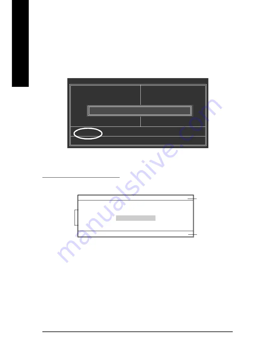
The Q-FlashBIOS utility screen consists of the following key components.

Task menu for Q-Flash utility:

Contains the names of three tasks. Blocking a task and pressing 

Enter 

key on your keyboard to enable

execution of the task.

Action bar:

Contains the names of four actions needed to operate the Q-Flash utility. Pressing the buttons mentioned
on your keyboards to perform these actions.

Q-Flash Utility V1.30

     Flash Type/Size..............................      SST 49LF002A

256K

Keep DMI Data

Enable

Update BIOS from Floppy

Save BIOS to Floppy

       Enter : Run             

hi

:Move               ESC:Reset              F10:Power Off

Q-Flash

TM

 utility bar

Action bar

Task menu  for
Q-Flash

TM

 utility

CMOS Setup Utility-Copyright (C) 1984-2003 Award Software

}

Standard CMOS Features

}

Advanced BIOS Features

}

Integrated  Peripherals

}

Power Management Setup

}

PnP/PCI Configurations

}

PC Health Status

}

Frequency/Voltage Control

ESC: Quit

higf

: Select Item

F8: Q-Flash

F10: Save & Exit Setup

Top  Performance

Load Fail-Safe Defaults

Load Optimized Defaults

Set Supervisor Password

Set User Password

Save & Exit Setup

Exit Without Saving

Enter Q-Flash Utility (Y/N)? Y

Summary of Contents for GA-8TRS350MT

Page 1: ...this card is 2X 3 3V The GA 8TRS350MT or anyAGP 4X 8X only motherboards might not functionproperly if you install this cardwithout switchingthejumper to 4X 1 5V mode in it Example 2 SomeATi Rage128 Pr...

Page 2: ...nt to update the information contained herein M Third party brands and names are the property of their respective owners M Please do not remove any labels on motherboard this may void the warranty of...

Page 3: ...Jun 25 2004 Mother Board GA 8TRS350MT...

Page 4: ...ations This device complies with part 15 of the FCC Rules Operation is subject to the following two conditions 1 This device may not causeharmful and 2 thisdevicemust accept anyinferencereceived inclu...

Page 5: ...USER S MANUAL GA 8TRS350MT P4 Titan Series Motherboard Pentium 4 ProcessorMotherboard Rev 1002 12ME 8TRS350MT 1002...

Page 6: ...U 10 Step 1 1 CPU Installation 10 Step 1 2 CPU Cooling Fan Installation 11 Step 2 Install memory modules 12 Step 3 Install expansion cards 15 Step 4 Install I O Peripherals Cables 16 Step 4 1 I O Back...

Page 7: ...fe Defaults 45 Load Optimized Defaults 45 Set Supervisor User Password 46 Save Exit Setup 47 Exit Without Saving 47 Chapter 4 Technical Reference 49 BIOSTM Introduction 49 Flash BIOS Method Introducti...

Page 8: ...parated fromthe system 5 Ensure thattheATXpower supplyis switched offbefore you plug in orremove theATX powerconnectoron themotherboard Ifthe motherboard has mountingholes buttheydon tline upwith the...

Page 9: ...66 DIMM Supports 128MB 256MB 512MB 1GB unbuffered DRAM Supports up to 4GB DRAM Max Note 1 Supports only2 5V DDR DIMM Slots 1 AGP slotsupports 8X 4X 1 5V mode 3 PCIslots support On Board IDE 2 IDE bus...

Page 10: ...volution detect CPU System Fan Control CPUOverheatWarning System Voltage Detect I O Control IT8712 PS 2 Connector PS 2 Keyboard interface and PS 2 Mouse interface BIOS Licensed AWARD BIOS Supports Q F...

Page 11: ...TRS350MT VGA COMA F_PANEL F_U SB1 PWR_LED PCI3 IT8712 IR CODEC F_U SB2 SPDIF_IO USB_LAN ATX_12V SOC KET478 FDD CLR_CMOS BAT SYS _FAN PCI2 BIOS ATi SB300 IXP 300 F_AUDIO CD_IN ATi RS350 IDE1 IDE2 AGP P...

Page 12: ...8 CPU ATiRS350 AC97 CODEC ATiSB300 IXP 300 CPUCLK 100 133 200 MHz System Bus 400 533 800MHz 266 333 400MHz ZCLK 66MHz HCLK 100 133 200 MHz 66MHz 33MHz 14 318MHz 48MHz 24MHz 33MHz LPC BUS AGP 4X 8X AGP...

Page 13: ...2 Install memory modules Step 3 Installexpansion cards Step 4 Install I O Peripherals Cables Chapter 2 Hardware Installation Process Congratulations you have accomplished the hardware installation Tur...

Page 14: ...ertthe CPU into the socket Angling the rod to 650 Socket Actuation Lever Pin1indicator 1 Angling therod to65 degree maybefeela kind oftight andthen continue pullthe rod to90 degree whena click noise i...

Page 15: ...PUsocketalone withthe cooling fan and mightdamage theprocessor Toavoidthis fromhappening wesuggestyouto eitheruse thermaltape insteadof thermalpaste orremove the cooling fanwith extremecaution 3 Make...

Page 16: ...module can only fitin one direction due to the one notches Wrong orientation willcause improper installation Please change the insertorientation Notch GA 8TRS350MT supports the Dual Channel Technology...

Page 17: ...her hand the memory module must be inserted into any sockets 3 Four DDR memory modules are installed Ifyou install four memory modules at the same time the Dual Channel Technology will operate only wh...

Page 18: ...e memory is a high performance and cost effective solution thatallows easy adoption for memory vendors OEMs and system integrators DDR memory is a greatevolutionary solution for the PC industry that b...

Page 19: ...card 6 Replaceyourcomputer s chassiscover 7 Power on the computer ifnecessary setup BIOS utility ofexpansion card from BIOS 8 Install related driver from the operating system AGPCard Please carefully...

Page 20: ...keyboard and PS 2 mouse Parallel Port TV Out and VGA Port LPT TVOut VGA This connectorsupports 1 TV Out 1 Parallel port and 1 VGA port Device like printer can be connected to Parallel port NTSC PAL TV...

Page 21: ...to Line In Connect Centerand Subwoofer to MICOut If you want the detail information for 2 4 6 channel audio setup installation please refer to page 61 USB LAN Connector Before you connectyour device...

Page 22: ...r Setting Introduction 3 1 8 2 9 11 18 13 17 16 5 6 7 12 15 10 1 ATX_12V 2 ATX 3 CPU_FAN 4 SYS_FAN 5 FDD 6 IDE1 IDE2 7 S_ATA1 S_ATA2 8 LED1 9 PWR_LED 10 2X_DET 11 F_PANEL 12 F_AUDIO 13 CD_IN 14 SPDIF_...

Page 23: ...U If theATX_12V power connector is not connected the system will not start Caution Please use a power supply that is able to handle the system voltage requirements It is recommended that a power suppl...

Page 24: ...ltage The black connector wire is the ground wire GND Please remember to connect the power to the cooler to preventsystem overheating and failure Caution Please remember to connectthe power to the CPU...

Page 25: ...d thatthe firsthard drive be connected to the IDE1 connector while the disk drive be connected to the IDE2 connector IDE1 IDE2 1 39 2 40 7 S_ATA1 S_ATA2 SerialATAConnector Serial ATAcan provide 150MB...

Page 26: ...rtor otherunexpected damages due to the 2 5Vstand by voltage Remove memorymodules only whenAC Power cord is disconnected 9 PWR_LED PWR_LED is connect with the system powerindicator to indicate whether...

Page 27: ...itch etc ofyour chassisfront panel to theF_PANEL connector according to the pin assignmentbelow HD IDEHard DiskActive LED Pin1 LEDanode Pin2 LED cathode SPEAK SpeakerConnector Pin 1 VCC Pin 2 Pin3 NC...

Page 28: ...assigment on the MB header To find out ifthe chassis youare buyingsupport frontaudio connector please contact yourdealer Please note you can have the alternative ofusing front audio connector or of us...

Page 29: ...carefully while you connect the SPDIF_IO cable incorrect connection between the cable and connector will make the device unable to work or even damage it For optional SPDIF_IO cable please contact you...

Page 30: ...work or even damage it For optional front USB cable please contact your localdealer 2 10 1 9 17 COMA COM AConnector White Be careful with the polarity of the COMA connector Check the pin assignment w...

Page 31: ...OFF the computerandunplugtheATX 12Vpowercord 2 EnableclearCMOSfunction 3 Plugthe ATX12Vpowercordand turnON the computer 1 1 19 BAT Battery If youwant to erase CMOS 1 TurnOFF thecomputerandunplugthepow...

Page 32: ...28 GA 8TRS350MTMotherboard English...

Page 33: ...andOutputSystem includes aCMOS SETUP utility which allows userto configure required settings or to activate certain system features The CMOS SETUP saves the configuration in the CMOS SRAM of the mothe...

Page 34: ...d BIOS CMOS Setup Utility theMain Menu as figure below will appear on the screen The MainMenu allows you toselectfrom eight setupfunctions and two exitchoices Use arrow keys to select among the items...

Page 35: ...heperformance of yoursystem set Top Performance as Enabled l Load Fail Safe Defaults Fail Safe Defaults indicates the value of the system parameters which the system would be in safe configuration l L...

Page 36: ...00 00 CMOS Setup Utility Copyright C 1984 2004 Aw ard Software Standard CMOS Features Date mm dd yy Mon May 3 2004 Time hh mm ss 22 31 24 IDE P rimary Master None IDE P rimary Slave None IDE Secondary...

Page 37: ...formation should be labeled on the outside drive casing Enter the appropriate option based on this information Cylinder Number of cylinders Head Number of heads Precomp Write precomp Landing Zone Land...

Page 38: ...t will stop for all other errors All But Disk Key The system boot will not stop for a keyboard or disk error it will stop for all other errors Memory The category is display only which is determined b...

Page 39: ...USB FDD USB ZIP Select your boot device priority by USB ZIP USB CDROM Select your boot device priority by USB CDROM USB HDD Select your boot device priority by USB HDD LAN Select your boot device prio...

Page 40: ...DE port On Chip Secondary PCI IDE Enabled Enable onboard 2nd channel IDE port Default value Disabled Disable onboard 2nd channel IDE port CMOS Setup Utility Copyright C 1984 2004 Aw ard Software Inte...

Page 41: ...use the internal graphics functionality and an external VGA card for display at the same time note The external VGA card you install must be built on ATI s graphics processor Disabled Disable this fu...

Page 42: ...llows you to determine which Infra Red IR function of Onboard I O chip ASKIR Set onboard I O chip UART to ASKIR Mode IrDA Set onboard I O chip UART to IrDA Mode Default value SCR Set onboard I O chip...

Page 43: ...ble PME Ring wake up function Default Value Disabled Disable this function USB Device Wake up From S3 Enabled Enable USB Device Wakeup From S3 Default value Disabled Disable USB Device Wakeup From S3...

Page 44: ...ystem KB Power ON Password Enter Input password from 1 to 5 characters and press Enter to set the Key board Power On Password AC BACK Function Memory System power on depends on the status before AC lo...

Page 45: ...gnment Auto Auto assign IRQ to PCI 3 Default value 3 4 5 7 9 10 11 12 14 15 Set IRQ 3 4 5 7 9 10 11 12 14 15 to PCI 3 CMOS Setup Utility Copyright C 1984 2004 Aw ard Software PnP PCI Configurations PC...

Page 46: ...n Default value CPU FAN Fail Warning Disabled Fan Warning Function Disable Default value Enabled Fan Warning Function Enable SYSTEM FAN Fail Warning Disabled Fan Warning Function Disable Default value...

Page 47: ...ency 400MHz Set CPU Clock to 100 132 for FSB Front Side Bus frequency 533MHz Set CPU Clock to 133 165 for FSB Front Side Bus frequency 800MHz Set CPU Clock to 200 232 Incorrect using it may cause your...

Page 48: ...h to maximize the performance of your system set Top Performance as Enabled Disabled Disable this function Default Value Enabled Enable Top Performance function CMOS Setup Utility Copyright C 1984 200...

Page 49: ...higf Selec t Item F8 Q Flash F10 Save Exit Setup Load Optimized Defa ults Top Perform ance Load Fail Sa fe Defa ults Load Optimized Defa ults Set Supervisor Password Set U ser Password Save Exit Setu...

Page 50: ...ll BIOS Setup program function When enabled the Supervisor password is required for entering the BIOS Setup program andhaving full configuration fields the User password is required to access only bas...

Page 51: ...Defa ults Set Supervisor Password Set U ser Password Save Exit Setup Exit Without Saving Save to CMOS and EXIT Y N Y Exit Without Saving Type Y will quit the Setup Utility without saving to RTC CMOS...

Page 52: ...48 GA 8TRS350MT Motherboard English...

Page 53: ...ware It could help you to download the BIOS from internetand update it Not like the other BIOS update software it s a Windows utility With the help of BIOS BIOS updating is no more than a click Beside...

Page 54: ...yte Technology Co Ltd is not responsible for damages of system because of incorrect manipulation of updating BIOS to avoid any claims from end users Before You Begin Before you start updating BIOS wit...

Page 55: ...dular BIOS v6 00PG An Energy Star Ally Copyright C 1984 2003 Award Software Inc Intel i875P AGPset BIOS for 8KNXP Ultra Fa3 Check System Health OK VCore 1 5250 Main Processor Intel Pentium R 4 1 6GHz...

Page 56: ...keyboard to enable execution of the task Task menu for Q Flash utility Contains the names of four tasks Blocking a task and pressing Enter key on your keyboard to enable execution of the task Action...

Page 57: ...rn Off Power Or Reset System 2 Move to the BIOS file you want to flash and press Enter In this example we only download one BIOS file to the floppy disk so only one BIOS file 8KNXPU Fba is listed Dual...

Page 58: ...OM Type Size SST 49LF004A 512K Wide Range Protection Disable Boot From Main Bios Auto Recovery Enable Halt On Error Disable Copy Main ROM Data to Backup Load Default Settings Save Settings to CMOS Q F...

Page 59: ...e Exit Setup Exit Without Saving CMOS Setup Utility Copyright C 1984 2003 Award Software Standard CMOS Features Advanced BIOS Features Integrated Peripherals Power Management Setup PnP PCI Configurati...

Page 60: ...le execution of the task Action bar Contains the names of four actions needed to operate the Q Flash utility Pressing the buttons mentioned on your keyboards to perform these actions Q Flash Utility V...

Page 61: ...Please confirm again you have the correct BIOS file for your motherboard 2 Move to the BIOS file you want to flash and press Enter In this example we only download one BIOS file to the floppy disk so...

Page 62: ...ll restart automatically after you exit Q Flash The BIOS file becomes Fab after updating After system reboots you may find the BIOS version on your boot screen becomes the one you flashed Q Flash Util...

Page 63: ...steps I Update BIOS through Internet a Click Internet Update icon b Click Update New BIOS icon c Select BIOSTM sever d Select the exact modelname on your motherboard e System will automatically downlo...

Page 64: ...very beginning there is About this program icon shown in dialog box It can help you check out which kind of motherboard and which brand of Flash ROM are supported Note a In method I if it shows two o...

Page 65: ...TEP 1 Connect the stereo speakers or earphone to Line Out The installation of Windows 2K XP is very simple Please follow next step to install the function Line Out STEP 3 Select Speaker Configuration...

Page 66: ...n on the taskbar s status area Click the audio icon Sound Effect from the windows tray at the bottom of the screen Line Out Line In STEP 3 Select Speaker Configuration and choose the 4 channel for 4 s...

Page 67: ...er Subwoofer channels to MIC In Basic 6 Channel Analog Audio Output Mode Line Out Line In MIC In STEP 2 After installation of the audio driver you ll find an icon on the taskbar s status area Click th...

Page 68: ...ce Audio Combo Kit provides SPDIF output port optical coaxis and SURROUND KIT Rear R L Center subwoofer SURROUND KIT access analog output to rear channels and Center Subwoofer channels It is the best...

Page 69: ...D KIT s REAR R L and the Center Subwoofer channels to SURROUND KIT s SUB CENTER STEP 5 Select Speaker Configuration and choose the 6 channel for 5 1 speakers out put Enable Only SURROUND KIT and press...

Page 70: ...output device to the rear bracket of PC and fix it with screw 2 Connect SPDIF wire to the motherboard A S PDIF output device is available on the motherboard Cable with rear bracket is provided and co...

Page 71: ...hers output devices to Line Out jack and microphone to MIC In jack Jack Sensing includes 2 parts AUTO and MANUAL Following is an example for 2 channels Windows XP Please connect the devices to the rig...

Page 72: ...Motherboard English Manual setting If the device picture shows different from what you set please press Manual Selection to set If you set wrong with the connectors the warning message will come out...

Page 73: ...t to return boot manager to NTFS format How to use the Xpress Recovery 1 Boot from CD ROM BMP Mode Enter the BIOS menu select Advanced BIOS Feature and set to boot from CD ROM Insert the provided driv...

Page 74: ...p speed 3 It is recommended that Xpress Recovery be immediately installed after OS and all requireddriver andsoftwareinstallations arecomplete AwardModularBIOSv6 00PG AnEnergyStarAlly Copyright C 1984...

Page 75: ...back to factory default or press Esc to exit Restores backup image to originalstate 3 Remove Backup Image Remove backup image Are you sure Y N Remove the backup image 4 Set Password Please input a 4 1...

Page 76: ...72 GA 8TRS350MT Motherboard English...

Page 77: ...age shows the drivers that need to be installed for the system Click each item to install the driver manually or switch to the to install the drivers automatically Massage Some device drivers will res...

Page 78: ...B device wake up S3 hang up issue in XP n RealTek LAN Driver RealTek 10 100 LAN driver for 81xx series chips n RealTekAC97 Audio Driver Install RealTekAC97 audio driver n USB 2 0 Driver It is recommen...

Page 79: ...theoverclocking and hardware monitoring functions n DMI Viewer Windows based utility which is used to browse the DMI SMBIOS information of the system n Face Wizard New utility for adding BIOS logo n...

Page 80: ...rd English SOFTWARE INFORMATION This page list the contects of softwares and drivers in this CD title HARDWARE INFORMATION This page lists all device you have for this motherboard CONTACT US Please se...

Page 81: ...RAID and ATA drivers under Win 2000 and XP on boards that support RAID function after I connect the boot HDD to IDE3 or IDE4 Answer First of all you need to save some files in the CD ROM to a floppy d...

Page 82: ...the user manual and check whether you have connected any cable that isnot provided with the motherboard package to the USB Over Current pin in the Front USB Panel If the cable is your own cable pleas...

Page 83: ...ode Answer Please set in the BIOS as follow 1 Advanced BIOS features SATA RAID SCSI boot order SATA 2 Advanced BIOS features First boot device SCSI 3 Integrated Peripherals Onboard H W ATA RAID enable...

Page 84: ...yratio voltage and etc are set properly Failure has been excluded Check if the CPU cooling fan attached to CPU properly ls CPU cooling fanpower connected to CPU_FAN properly Plug the CPU cooling fan p...

Page 85: ...tw The appropriate response will be provided ASAP Is memoryLED on and CPUfan running The problem could be caused by power supply CPU memory or CPU memory socket itself Check if there is display Perha...

Page 86: ...Phone No ContactPerson E mail Add Model name Lot Number PCB revision BIOS version O S A S Hardware Mfs Model name Size Driver Utility Configuration CPU Memory Brand Video Card Audio Card HDD CD ROM D...

Page 87: ...munication and Networking Riser DMA Direct Memory Access DMI DesktopManagementInterface DIMM Dual Inline Memory Module DRM DualRetentionMechanism DRAM Dynamic Random Access Memory DDR DoubleDataRate E...

Page 88: ...ingDiode MHz Megahertz MIDI MusicalInstrument DigitalInterface MTH Memory Translator Hub MPT MemoryProtocol Translator NIC Network Interface Card OS Operating System OEM OriginalEquipmentManufacturer...

Page 89: ...85 Memo English...

Page 90: ...86 GA 8TRS350MT Motherboard English...

Page 91: ...87 Memo English...

Page 92: ...88 GA 8TRS350MT Motherboard English...

Page 93: ...89 Memo English...

Page 94: ...90 GA 8TRS350MT Motherboard English...

Page 95: ...pport http de giga byte com TechSupport ServiceCenter htm Non Tech Support Sales Marketing http ggts gigabyte com tw nontech asp WEB address http www gigabyte de Japan NIPPONGIGA BYTE CORPORATION WEB...

Page 96: ...5616288 FAX 61 3 85616222 Tech Support http www giga byte com au TechSupport ServiceCenter htm Non Tech Support Sales Marketing http ggts gigabyte com tw nontech asp WEB address http www giga byte com...

Reviews: