


System Hardware Installation
- 36 -
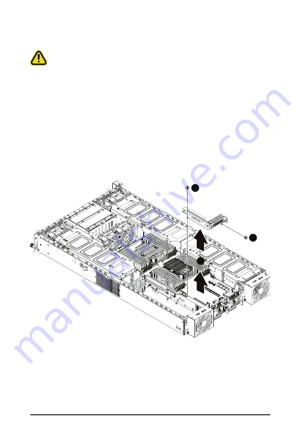
3-6 Installing a PCI Express Card
• Voltages can be present within the server whenever an AC power source is connected. This
voltage is present even when the main power switch is in the off position. Ensure that the system
is powered-down and all power sources have been disconnected from the server prior to installing
a PCI card.
Failure to observe these warnings could result in personal injury or damage to equipment.
Follow these instructions to install a PCI Express x8 card on right side of the
system:
1. Loosen and remove the two screws securing the PCI Express card bracket on the right side of the
system.
2. Remove the PCI Express card bracket from the system.
3. Install the PCI Express card into the bracket.
4. Secure the PCI Express card to the bracket with one screw.
5. Install the PCI Express card bracket with card back into the system, ensure that the connector on
the bracket is securely installed into the connector on the motherboard as shown.
6. Secure the PCI Express card bracket with card to the system with two (2) screws.
2
1
1
Summary of Contents for G292-Z45
Page 1: ...G292 Z45 HPC Server 2U DP 8 x Gen4 GPU Server User Manual Rev 1 0 ...
Page 10: ... 10 This page intentionally left blank ...
Page 15: ... 15 Hardware Installation 1 3 System Block Diagram ...
Page 16: ...Hardware Installation 16 This page intentionally left blank ...
Page 27: ... 27 System Hardware Installation 2 3 1 4 CPU0 CPU1 ...
Page 32: ...System Hardware Installation 32 For GPU7 1 2 2 For GPU1 Front Rear 1 ...
Page 33: ... 33 System Hardware Installation 1 2 2 3 4 ...
Page 35: ... 35 System Hardware Installation 1 1 2 2 For GPU4 1 1 2 2 3 4 ...
Page 37: ... 37 System Hardware Installation 3 4 5 6 6 ...
Page 39: ... 39 System Hardware Installation 5 6 ...
Page 41: ... 41 System Hardware Installation ...
Page 48: ...System Hardware Installation 48 CPU Power MB Top Tray Connector 1 x 3 Power ...
Page 49: ... 49 System Hardware Installation HDD Backplane Board Signal HDD Backplane Board Power ...
Page 50: ...System Hardware Installation 50 Power Distribution Board to HDD Backplane Board Power SMD ...
Page 52: ...System Hardware Installation 52 Front Panel IO NVMe ...
Page 53: ... 53 System Hardware Installation NVMe Bo om Connector ...
Page 54: ...System Hardware Installation 54 NVMe Bo om Connector ...
Page 58: ...Motherboard Components 58 This page intentionally left blank ...
Page 64: ...BIOS Setup 64 When Boot Mode Select is set to Legacy in the Boot Boot Mode Select section ...
Page 69: ... 59 BIOS Setup 5 2 4 1 Serial Port 1 2 Configuration ...
Page 77: ... 59 BIOS Setup 5 2 8 PCI Subsystem Settings ...
Page 87: ...BIOS Setup 87 5 2 16 Intel R I350 Gigabit Network Connection ...
Page 151: ...BIOS Setup 151 This page intentionally left blank ...


