


System Appearance
- 19 -
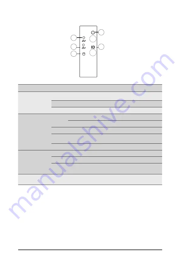
2-3 Front Panel Buttons and LEDs
No. Name
Color
Status
Description
1/2.
LAN1/2
Active/
Link LED
Green
On
Indicates a link between the system and the network or
no access.
Green
Blink
Indicates data trasmission or receiving is occuring.
N/A
Off
Indicates no data transmission or receiving is occuring.
3.
HDD Status
LED
Green
On
Indicates locating the HDD.
Blink
Indicates accessing the HDD.
Amber
On
Indicates HDD error.
Green /
Amber
Blink
Indicates HDD rebuilding.
N/A
Off
Indicates no HDD access or no HDD error.
4.
Power Button
with LED
Green
On
Indicates the system is powered on.
Green
Blink
System is in ACPI S1 slate (sleep mode).
N/A
Off
Indicates system is not powered on or in ACPI S5 slate
(power off) or system is in ACPI S4 slate (hibernation mode).
5.
ID Button
with LED
--
--
Press this button to activate system identification.
1
2
3
4
5
Summary of Contents for G292-Z20
Page 10: ... 10 ...
Page 27: ... 27 System Hardware Installation 2 2 1 1 3 3 4 4 ...
Page 35: ... 35 System Hardware Installation 1 2 2 3 4 ...
Page 37: ... 37 System Hardware Installation 1 2 2 For GPU3 GPU4 1 1 2 2 3 4 ...
Page 48: ...System Hardware Installation 48 CPU Power MB Top Tray Connector 1 x 3 Power ...
Page 49: ... 49 System Hardware Installation HDD Backplane Board Signal HDD Backplane Board Signal ...
Page 51: ... 51 System Hardware Installation SlimLine SAS 2 MB Top Tray Connector Front Panel IO ...
Page 52: ...System Hardware Installation 52 SMD ...
Page 56: ...Motherboard Components 56 This page intentionally left blank ...
Page 62: ...BIOS Setup 62 When Boot Mode Select is set to Legacy in the Boot Boot Mode Select section ...
Page 67: ... 67 BIOS Setup 5 2 4 1 Serial Port 1 2 Configuration ...
Page 75: ... 75 BIOS Setup 5 2 8 PCI Subsystem Settings ...
Page 85: ...BIOS Setup 85 5 2 16 Intel R Ethernet Controller XI350 ...
Page 149: ...BIOS Setup 149 This page intentionally left blank ...


