


System Hardware Installation
- 34 -
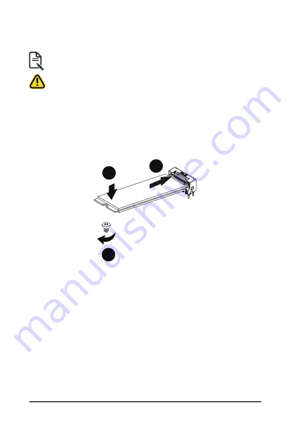
3-8 Installing and Removing an M.2 Solid State Drive
Follow these instructions to install an optional M.2 solid state drive (SSD):
CAUTION
The position of the stand-off screw will depend on the size of the M.2 device. The stand-off screw
is pre-installed for 22110 cards as standard. Refer to the size of the M.2 device and change the
position of the stand-off screw accordingly.
1. Place the solid state drive into the M.2 connector.
2. Secure the solid state drive to the motherboard with a single screw.
NOTE:
The position of the screw will depend on the size of the SSD. Refer to the second image
below for proper placement.
3. Reverse steps 1-2 to remove the solid state drive.
1
2
3
NOTE:
To install/remove the M.2 heatsink use a No. 1 Phillips-head screwdriver with a screw torque of
1.5 ± 0.2 kgf*cm
Summary of Contents for G242-P33
Page 14: ...Hardware Installation 14 1 3 System Block Diagram 1 3 1 G242 P33 ...
Page 15: ... 15 Hardware Installation 1 3 2 G242 P34 ...
Page 16: ...Hardware Installation 16 This page intentionally left blank ...
Page 27: ... 27 System Hardware Installation 4 2 3 1 6 ...
Page 41: ... 41 System Hardware Installation ...
Page 42: ...System Hardware Installation 42 GPU Signal Cable ...
Page 45: ... 45 System Hardware Installation System Main Power Cable MB Bo om Power Connector ...
Page 48: ...System Hardware Installation 48 GPU Signal Cable MB Bo om Power Connector ...
Page 50: ...System Hardware Installation 50 This page intentionally left blank ...
Page 54: ...Motherboard Components 54 This page intentionally left blank ...
Page 65: ... 65 BIOS Setup 5 2 6 PCI Subsystem Settings ...
Page 69: ... 69 BIOS Setup 5 2 6 2 PCI Express GEN 2 Settings ...
Page 79: ... 79 BIOS Setup 5 2 14 Intel R I350 Gigabit Network Connection ...