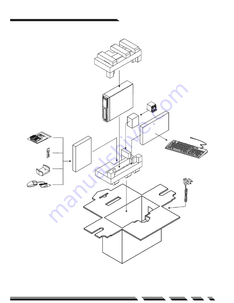
G-MAX
TM
Flex ATX Series Us er’s Manual
P. E3
Sof tware and Manuals
Ca bles
Pow er Cord
PC
Foot Stand
Mouse (Opt ion)
Keyboard (Option)
P4 CPU c ooler (Option)
Ite ms included in the pa cka ge
Page 1: ...y errors or omissions that may appear in this document nor does the author make a commitment to update the informationcontained herein Third party brands and names are the property of their respective...
Page 2: ...m water heat and dust Before connecting any peripheral equipment please unplug the power cord from the system unit to prevent unexpected damage The AC input supplies power to the system unit Check you...
Page 3: ...G MAX TM Flex ATX Series User s Manual P E3 Sof tware and Manuals Cables Pow er Cord PC Foot Stand Mouse Opt ion Keyboard Option P4 CPU cooler Option Items included in the package...
Page 4: ...Motherboard Manual for details III Power Supply The ATX switching power supply included with this product supports soft off function Hence the system can be shut down automatically Default input volta...
Page 5: ...ver to lock the CPU on thesocket after installation 3 3 Apply thermal grease to the top of the CPU Thermal grease should cover the entire surface of the integrated heat spreader Make sure that you sho...
Page 6: ...Setup if needed see Motherboard Manual for details 4 Memory Click cooler lock on the pin at sides of CPU socket Install cooler on top of CPU Power Supply Notches at sides of module Position notches M...
Page 7: ...ection we will guide you to install memory module First make sure the position notches at the bottom of the module should align to the pins on the module sockets on the motherboard then push the modul...
Page 8: ...accessory box to the connector on the hard disc Make sure that the RED wire on the ribbon should be connected to PIN 1 of hard drive 7 Connect power connector to the hard disc 8 Put the assembled HDD...
Page 9: ...lat cables 9 Connect another end of the IDE connector to the IDE 1 bus on the motherboard 10 Put the assembled HDD frame back to the chassis and tighten the screws to the chassis 11 Put the front pane...
Page 10: ...s Manual P E10 V System Installation and User s Guide Front Panel PCMCIA Button Floppy PCMCIA Port 1394 Hub SPDIF CD ROM Tray CD ROM Button Power Button Power LED HDD LED Audio Out MIC In USB Hub 2 0...
Page 11: ...t Safety Instructions Caution T o reduce the risk of fire use only No 26AWG or larger telephone line cord Caution Always disconnect all telephone lines from the wall outlet before servicing or disasse...
Page 12: ...SPDIF only 1 Insert the Driver CD that was included in accessory box into your CD ROM Install or upgrade the audio driver 2 If SPDIF can t output normally after audio driver is updated please operate...
Page 13: ...G MAX TM Flex ATX Series User s Manual P E13 B Volume Control Options Advanced Controls Properties Playback SPDIF OK Select Select Enable Select Add...
Page 14: ...Series User s Manual P E14 C Select SPDIF Advanced Sampling rate conversion for SPDIF output Close Finish 3 Similar procedures will be applied to different Windows operating systems to enable the SPDI...
Page 15: ...CD audio 1 Insert the Driver CD that was included in accessory box into your CD ROM Install or upgrade the audio driver 2 If the digital CD audio can t output normally after audio driver is updated p...
Page 16: ...G MAX TM Flex ATX Series User s Manual P E16 C Select Hardware Device Manager...
Page 17: ...G MAX TM Flex ATX Series User s Manual P E17 D Select DVD CD ROM drivers Properties E Select Enable digital CD audio for this CD ROM device OK...
Page 18: ...8 F Select YES 3 The Enable digital CD audio for this CD ROM device option in Windows ME and Windows XP is default set to Enable 4 Similar procedures will be applied to different Windows operating sys...