background image

- 15 -

2-5  Installing an Expansion Card

Read the following guidelines before you begin to install an expansion card:


Make sure the motherboard supports the expansion card. Carefully read the manual that came 

with your expansion card.


Always turn off the computer and unplug the power cord from the power outlet before installing an 

expansion card to prevent hardware damage.

Follow the steps below to correctly install your expansion card in the expansion slot.

1.  Locate an expansion slot that supports your card. Remove the metal slot cover from the chassis back panel.

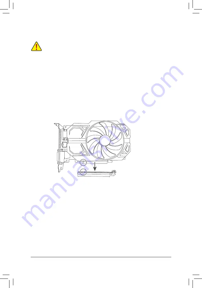
2.  Align the card with the slot, and press down on the card until it is fully seated in the slot.

3.  Make sure the metal contacts on the card are completely inserted into the slot.

4.  Secure the card's metal bracket to the chassis back panel with a screw.

5.  After installing all expansion cards, replace the chassis cover(s).

6.  Turn on your computer. If necessary, go to BIOS Setup to make any required BIOS changes for your 

expansion card(s).

7.  Install the driver provided with the expansion card in your operating system.

PCIEX16 Slot

Summary of Contents for B660M D3H DDR4

Page 1: ...ease visit GIGABYTE s website To reduce the impacts on global warming the packaging materials of this product are recyclable and reusable GIGABYTE works with you to protect the environment B660M D3H D...

Page 2: ...may be reproduced copied translated transmitted or published in any form or by any means without GIGABYTE s prior written permission In order to assist in the use of this product carefully read the Us...

Page 3: ...3 Installing the CPU and CPU Cooler 11 2 4 Installing the Memory 14 2 5 Installing an Expansion Card 15 2 6 Back Panel Connectors 16 2 7 Internal Connectors 18 Chapter 3 BIOS Setup 30 Chapter 4 Instal...

Page 4: ...EC CLR_CMOS RST U32_LAN PCIEX16 PCIEX1 iTE Super I O Intel 2 5 GbE LAN LED_C F_USB1 SYS_FAN3 SPI_TPM F_PANEL SATA3 7 6 VGA HDMI 80 60 60 80 M_BIOS LPT QFLASH_PLUS RST_SW F_U32 U32G2C U32G2 M2P_SB M2A_...

Page 5: ...erboard 5 5 User s Manual 5 5 Two SATA cables 5 5 M 2 screws 5 5 I O Shield The box contents above are for reference only and the actual items shall depend on the product package you obtain The box co...

Page 6: ...atic electricity Prior to installing the motherboard please have it on top of an antistatic pad or within an electrostatic shielding container Before connecting or unplugging the power supply cable fr...

Page 7: ...Hz 1 x HDMI port supporting a maximum resolution of 4096x2160 60 Hz Support for HDMI 2 0 version and HDCP 2 3 1 x DisplayPort supporting a maximum resolution of 4096x2304 60 Hz Support for DisplayPor...

Page 8: ...2 ports available through the internal USB header 2 x USB 2 0 1 1 ports on the back panel Chipset USB 2 0 Hub 4 x USB 2 0 1 1 ports available through the internal USB headers Internal Connectors 1 x 2...

Page 9: ...warning Fan speed control Whether the fan speed control function is supported will depend on the fan you install BIOS 1 x 256 Mbit flash Use of licensed AMI UEFI BIOS PnP 1 0a DMI 2 7 WfM 2 0 SM BIOS...

Page 10: ...the latest version of apps Bundled Software Norton Internet Security OEM version LAN bandwidth management software Operating System Support for Windows 11 64 bit Support for Windows 10 64 bit Form Fa...

Page 11: ...y occur Set the CPU host frequency in accordance with the CPU specifications It is not recommended that the system bus frequency be set beyond hardware specifications since it does not meet the standa...

Page 12: ...en the metal load plate with the plastic protective cover attached to it Hold the CPU with your fingers by the edges Align the CPU pin one marking triangle with the pin one corner of the CPU socket or...

Page 13: ...user s manual for your CPU cooler u v Apply an even and thin layer of thermal grease on the surface of the installed CPU Place the cooler atop the CPU aligning the four push pins through the pin hole...

Page 14: ...the BIOS will automatically detect the specifications and capacity of the memory Enabling Dual Channel memory mode will double the original memory bandwidth The four memory sockets are divided into t...

Page 15: ...pansion slot 1 Locate an expansion slot that supports your card Remove the metal slot cover from the chassis back panel 2 Align the card with the slot and press down on the card until it is fully seat...

Page 16: ...ms You can use this port to connect your DisplayPort supported monitor Note The DisplayPort Technology can support a maximum resolution of 4096x2304 60 Hz but the actual resolutions supported depend o...

Page 17: ...The Gigabit Ethernet LAN port provides Internet connection at up to 2 5 Gbps data rate The following describes the states of the LAN port LEDs USB 3 2 Gen 1 Port The USB 3 2 Gen 1 port supports the U...

Page 18: ...tlet to prevent damage to the devices After installing the device and before turning on the computer make sure the device cable has been securely attached to the connector on the motherboard 1 ATX_12V...

Page 19: ...meet expansion requirements it is recommended that a power supply that can withstand high power consumption be used 500W or greater If a power supply is used that does not provide the required power t...

Page 20: ...o Definition 1 GND 2 Voltage Speed Control 3 Sense 4 PWM Speed Control CPU_FAN 1 1 SYS_FAN1 1 SYS_FAN2 SYS_FAN3 Connector CPU_FAN SYS_FAN1 3 Maximum Current 2A 2A Maximum Power 24W 24W 5 LED_C RGB LED...

Page 21: ...rip header Incorrect connection may lead to the damage of the LED strip Addressable LED Strip 1 7 SATA3 4 5 6 7 SATA 6Gb s Connectors TheSATAconnectorsconformtoSATA6Gb sstandardandarecompatiblewithSAT...

Page 22: ...eeded move the standoff to the desired mounting hole Insert the M 2 SSD into the M 2 connector at an angle Step 2 Press the M 2 SSD down and then use the included screw to secure it in the connector T...

Page 23: ...em startup status by issuing a beep code One single short beep will be heard if no problem is detected at system startup HD Hard Drive Activity LED Connects to the hard drive activity LED on the chass...

Page 24: ...separated connectors on each wire instead of a single plug For information about connecting the front panel audio module that has different wire assignments please contact the chassis manufacturer 11...

Page 25: ...2x5 pin cable into the USB 2 0 1 1 header Prior to installing the USB bracket be sure to turn off your computer and unplug the power cord from the power outlet to prevent damage to the USB bracket Pi...

Page 26: ...TS 9 NRI 10 No Pin 2 1 10 9 15 LPT Parallel Port Header The LPT header can provide one parallel port via an optional LPT port cable For purchasing the optional LPT port cable please contact the local...

Page 27: ...B B B_ B_ F_USB3 F_USB30 3 _ _3 U S _ S S_F _ _ F 1 1 THB_C2 THB_C1 17 SPDIF_O S PDIF Out Header This header supports S PDIF digital output which allows you to connect a S PDIF digital audio cable to...

Page 28: ...rform different tasks please navigate to the BIOS Setup page of GIGABYTE s website and search for RST_SW MULTIKEY for more information 18 CLR_CMOS Clear CMOS Jumper Use this jumper to clear the BIOS c...

Page 29: ...accurate or may be lost You may clear the CMOS values by removing the battery 1 Turn off your computer and unplug the power cord 2 Gently remove the battery from the battery holder and wait for one m...

Page 30: ...downloads the latest version of BIOS from the Internet and updates the BIOS For instructions on using the Q Flash and BIOS utilities please navigate to the Unique Features page of GIGABYTE s website a...

Page 31: ...or the down arrow key i to select the first boot device then press Enter to accept The system will boot from the device immediately Note The setting in Boot Menu is effective for one time only After s...

Page 32: ...website browse to the motherboard model s web page download the Intel SATAPreinstall driver file on the Support Download SATA RAID AHCI page unzip the file and copy the files to your USB thumb drive S...

Page 33: ...Settings IO Ports APP Center Download Install Configuration APP Center Download Install is set to Enabled Please visit GIGABYTE s website for more software information Please visit GIGABYTE s website...

Page 34: ...rformance it is recommended that you use two hard drives with identical model and capacity Windows setup disc An Internet connected computer A USB thumb drive Please visit GIGABYTE s website for detai...

Page 35: ...symbol shown below is on the product or on its packaging which indicates that this product must not be disposed of with other waste Instead the device should be taken to the waste collection centers...

Page 36: ...2 8912 4000 FAX 886 2 8912 4005 Tech and Non Tech Support Sales Marketing https esupport gigabyte com WEB address English https www gigabyte com WEB address Chinese https www gigabyte com tw GIGABYTE...

Reviews: