8
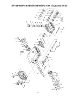
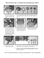
8. With a valve puller remove
the valve seat (37) and o-ring
(38) replace if worn. If exces-
sive pitting is seen, replace
the worn parts. Check valve
seat o-ring (38) for wear and
replace as necessary.
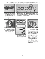
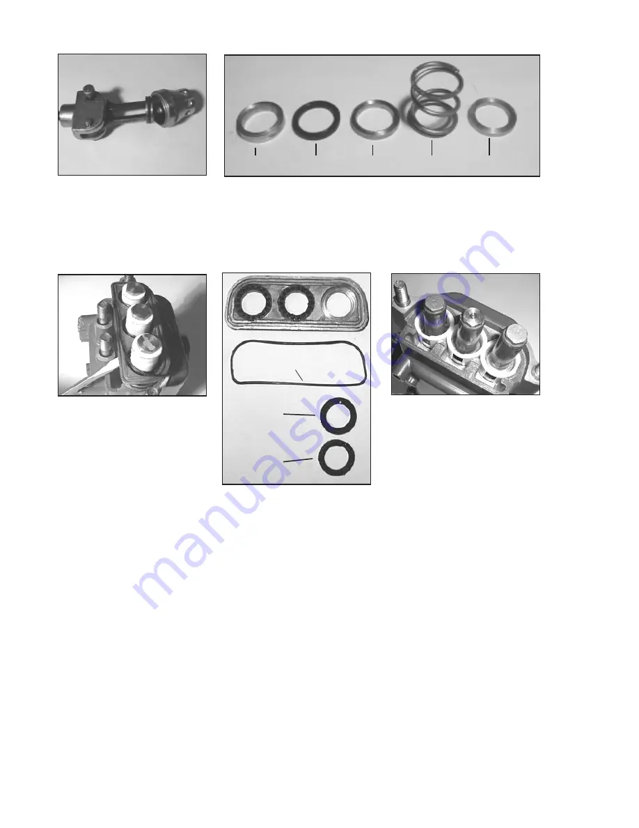
9. Remove the spacer (39A), pressure spring (33), support ring (32
or 31A for SP100HK), v-sleeve (31), and pressure ring (30), from
the manifold (29) and check for wear.
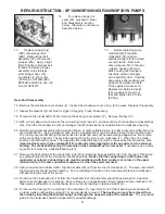
10.
With a flat headed screw-
driver remove the weep return
plate (48). Remove the o-ring
(49) and check for wear.
11. Inspect seals (50), seal sup-
port ring (51) and O-ring (49)
and replace as necessary.
49
50
51
12.
Inspect ceramic plunger
(24A) tips for wear. If neces-
sary, replacement of the
ceramic plungers may be ac
-
complished by removing the
plunger bolt assemblies (24)
with a 13mm wrench. Ce-
ramic plungers should now
slide off the stainless steel
plunger base (22). Exces-
sive resistance to plunger
removal may be overcome
by heating the stainless steel
plunger base. This will melt
any excess loc-tite beneath
the ceramic plunger allowing
easy removal.
30
31
32
33
39A
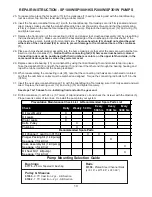
REPAIR INSTRUCTION - SP100W/SP100HK/SP200W/SP351W PUMPS
31A for SP100HK


