background image

7

GP7132  AND GP7136 REPAIR INSTRUCTIONS

NOTE:

Always take time to lubricate all metal and non-metal parts with a light film of oil

before reassembling.  This step will help ensure proper fit, at the same time protecting

the pump non-metal parts (elastomers) from cutting and scoring.

1.

Lossen screws (58C), take

plugs (58) out of valve cas-

ing with two screws.

2.

Take out complete valve

(51) using either tool (part

#07662) or stud bolt.

3.

Valve seats (51C and 52C)

are pressed out of spacer

pipe (51F) by hitting the

valve plate (51D) with a

bolt.

4.

Check surfaces of valve plate, valve seat, O-rings (51B, 58A) and

replace worn parts.

5.

When reassembling: The

suction valve seat (51C) is

1mm smaller in diameter than

the discharge valve seat

(52C). Suction valve seats

are marked "S" and always

have to be installed first. Dis-

charge valve seats are

marked "P" and are always

tobe installed on top of suc-

tion valve. Plugs (58) are to

be tensioned down evenly

with screws (58C) and

crosswise at

155 ft-lbs.

51F

51E

51C

51B

51A

51C or 52C

or 52C

P

S

6.

Loosen nuts (49A)

7.

Remove pump head.

Summary of Contents for GP7132

Page 1: ... InstallationInstructions page 2 Pump Specifications GP7132 page 3 Exploded View page 4 Parts List Kits page 5 Pump Specifications GP7136 page 6 Repair and Service pages 7 9 Torque Specs page 9 TroubleShootingChart page 10 Recommended Spare Parts List page 10 Dimensions page 11 WarrantyInformation back page ...

Page 2: ...erious injury 2 Pump operation must not exceed rated pressure volume or RPM A pressure relief device must be installed in the discharge of the system 3 Acids alkalines or abrasive fluids cannot be pumped unless approval in writing is obtained before operation from Giant Industries Inc 4 Run the pump dry approximately 10 seconds to drain the water before exposure to freezing temperatures IMPORTANT ...

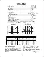
Page 3: ...nkshaft Diameter 48mm KeyWidth 14mm Crankshaft Mounting Either side Shaft Rotation Top of pulley towards manifold Temperature of Pumped Fluids Up to 140 o F Inlet Ports 2 1 1 4 NPT Discharge Ports 2 3 4 NPT Weight 374 lbs Crankcase Oil Capacity 1 6 Gal Fluid End Material Stainless Steel Volumetric Efficiency 700 RPM 94 Mechanical Efficiency 700 RPM 83 Specifications Model GP7132 HORSEPOWER RATINGS...

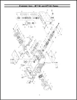
Page 4: ...4 Exploded View GP7132 and GP7136 Pumps ...

Page 5: ...ure Ring GP7132 3 41 06795 Pressure Ring GP7136 3 42 06096 V Sleeve GP7132 6 42 06796 V Sleeve GP7136 6 43 06097 Sleeve Support Ring GP7132 3 43 06797 Sleeve Support Ring GP7132 3 45 06098 Tension Spring 3 49 13159 Stud Bolt 8 49A 13160 Nut 8 50 06798 Valve Casing 1 50A 13162 Cylinder Stud 2 51 13146 Inlet Valve Assy 3 51A 12056 Support Ring 6 51B 07354 O Ring 6 51C 13131 Inlet Valve Seat 3 51D 13...

Page 6: ...fold Temperature of Pumped Fluids Up to 140 o F Inlet Ports 2 1 1 4 NPT Discharge Ports 2 3 4 NPT Weight 374 lbs Crankcase Oil Capacity 1 6 Gal Fluid End Material Stainless Steel Volumetric Efficiency 700 RPM 94 Mechanical Efficiency 700 RPM 83 Specifications Model GP7136 HORSEPOWER RATINGS The rating shown are the power requirements for the pump Gas engine power outputs must be approximately twic...

Page 7: ...ts 51C and 52C are pressed out of spacer pipe 51F by hitting the valve plate 51D with a bolt 4 Check surfaces of valve plate valve seat O rings 51B 58A and replace worn parts 5 When reassembling The suction valve seat 51C is 1mmsmallerindiameterthan the discharge valve seat 52C Suction valve seats are marked S and always havetobeinstalledfirst Dis charge valve seats are marked P and are always tob...

Page 8: ...ace with new parts Examine plunger 36 for wear 38A 38B 38 38B 38A 36 11 Takeathinscrewdriverandpryoutthegroovedring 39A Note This seal 39A will not be reusable so replace with a new part Fortheseal pack 41 43 removewitheitherasocketwrench or use a screw driver to push against the rear lip of the pressure ring 41 or v sleeves 42 You will need to remove seals evenly out of the seal sleeve 39 Be care...

Page 9: ...ng studs 50A Tighten nuts 49A to103 ft lbs TO DISASSEMBLE GEAR 14 Take out plunger 36 and seal sleeves 39 as described above Drain oil 15 After removing the circlip ring 33B lever out seal retainer 33 with a screw driver Check seals 32 32A 33A and surfaces of crosshead 16 Remove crankcase cover 4 Loosen inner hexagon screws on the connecting rods 24 and push con rod halves as far into the crosshea...

Page 10: ...aks correctly sized inlet plumbing to pump Accumulator pressure Recharge Replaceaccumulator Unloader Check for proper operation Cavitation Check inlet lines for restrictions and or proper size Pump Pressure as Restricted discharge plumbing Re size discharge plumbing to Drop at gun flow rate of pump Rated Pressure Excessive Worn plungers Replace plungers Leakage Worn packing seals Adjust or Replace...

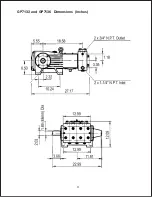
Page 11: ...11 GP7132 and GP7136 Dimensions Inches ...

Page 12: ... or modifications made by the customer or third party 6 The operation of pumps and or accessories exceeding the specifications set forth in the Operations Manuals provided by Giant Industries Inc Liability under this warranty is on all non wear parts and limited to the replacement or repair of those products returned freight prepaid to Giant Industries which are deemed to be defective due to workm...

Reviews: