7
To Check Valves
Remove inner hexagon screw (48A) and remove plugs (48) with a screwdriver. Check O-rings on plugs (48).
Pull out tension spring (48C). Remove the spring tension disc (47F) from discharge valve lying underneath by
screwing in the M10-screw. Take out spring (47E) and plate (47D). Pull out valve seat (47C) by means of an
valve puller. Check sealing areas of plate and valve seat for damage and replace worn parts. Check O-rings
(47A) and (47B). Screw spacer pipe (46G) out of spring tension cap (46F) in the suction valve lying underneath.
Remove suction valve by screwing in an M10-screw. Check O-ring (46A) and (46B). If valve seat (46C) remains
in the valve casing (43) then carry forth as described for discharge valve. When reassembling, use new O-rings
if possible and oil them before installing.
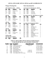
Tighten inner hexagon screws (48A) to 35 ft.-lbs. (47 Nm).
To Check Seals and Plunger Pipe
Loosen the inner hexagon screws (49) and pull off valve casing (43) to the front. Pull seal sleeves (35) out of
guides in crankcase and over the plunger pipe (29B). Pull support ring (41), sleeves (40) and pressure ring (39)
out of seal sleeve.
Check plunger surfaces, sleeves (40) and grooved rings (36). Replace worn parts.
If the plunger pipe is worn out, loosen tension screw (29C) and pull off plunger pipe to the front. Clean contact
surfaces of plunger (25) thoroughly. Then place new plunger pipe carefully through the oiled seals into the seal
case. Check o-rings on seal sleeves and seal case (GP5132/GP5132-SSP only) and replace worn o-rings. Then
push seal sleeve together with plunger pipe into the crankcase guide. Turn gear carefully until plunger (25) comes
up against the plunger pipe. Put a new copper gasket (29D) onto the tension screw (29C). Cover the thread of
tension screw and the gasket with glue and tighten to 29 ft.-lbs. (30 Nm).
Important!
Care must be taken that no glue gets between the plunger pipe (29B) and the centering sleeve
(29A). The plunger pipe should not be strained by eccentric tightening of the tension screw or through damage
to front of surface of plunger, otherwise it will probably break. Tighten the inner screws (49) for the valve casing
evenly to 89 ft.-lbs. (120 Nm).
To Dismantle Gear
Drain oil after dismantling valve case and plunger pipes and screw off crankcase cover (4) and bearing cover
(14).
Loosen con rod screws (24), push stem of con rod as far as possible into the crosshead guide and carefully
push out the radial shaft seals (31).
Important!
Connecting rods are marked for identification. Do not twist con rod halves. Con rod is to be reinstalled
in the same position on shaft journals.
While slightly turning the crankshaft, hit it out carefully to one side with a rubber hammer.
Important!
Do not bend con rod shank. Finally, check surfaces of shaft, con rod, crosshead and plungers (25)
as well as radial shaft seals (15, 31) and taper roller bearings (20).
To Reassemble
Using a soft tool, press in the outer bearing ring until it lines up with the outer edge of the bearing hole. Remove
bearing cover together with shaft ring and O-ring. Fit shaft with pressed-on bearing parts through the bearing
hole on the opposite side. Press in outer bearing ring and tension it inwards with the bearing cover, keeping the
shaft in vertical position and turning it slowly so that the taper rollers of the bearings touch the edge of the outer
bearing ring. Adjust axial bearing clearance with fitting discs 0.1mm (20A). Shaft should turn easily with very
little clearance. Tighten inner hexagon screws on con rod (24) to 22 ft.-lbs. (30 Nm).
Important!
There should be enough clearance for the con rod to move sideways a little on the journals.
Important!
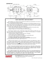
The 1/2” BSP connection in the crankcase serves the purpose of
draining leakage water. The connection should not be closed (see the drawing
to the right).
GP5132, GP5132-SSP, GP5136, GP5142 and GP5145 REPAIR INSTRUCTIONS


