background image


5


maintenance 

 
GENERAL: 


 Follow 

implicitly

 the engine manufacturer’s recommendations for maintenance. 


  Always keep your machine clean - especially the engine.  Check all adjustments periodically.  Also, 

periodically check that all fasteners are secure.   


Never make any adjustments to the unit until the engine is 

off 

and the spark plug wire is disconnected. 


If carburetor adjustment is necessary, stand to one side and 

keep feet and hands

 in the clear while making 

adjustments. 


  Keep engine free of accumulations of grass, leaves or excessive grease.  An accumulation of these 

combustible materials may result in a fire. 


Store gasoline in a 

safe and approved

 container in a cool, dry place. 


Keep the unit and any fuel containers in locked storage to prevent children from playing and/or tampering 
with them. 


  Do not store gasoline powered equipment or fuel containers in a basement or any closed area where 

heating or heat appliances or open pilot lights are present, unless the fuel is completely drained from the 
power equipment and the fuel containers. 

 
LUBRICATION: 


The pneumatic tires on your blower contain bearings that should be lubricated on a weekly basis using a 
high-performance, automotive quality grease to ensure long life and minimal wear. 

Summary of Contents for LBX10151BV

Page 1: ...MANUAL PARTS LIST Manual 3071775 Rev 1 04 30 04 Walk Behind Leaf Blower EXTREME II SERIES 1 Actual product may differ from product pictured above Models covered LBX10151BV 3085656 LBX85151KH 3085658 LBX9151H 3085659 LBX13151KH 3085657 ...

Page 2: ...ll out and return the warranty registration enclosed in your manual packet Your new blower requires very little assembly Simply follow the instructions contained within this manual to begin enjoying the benefits of your new unit CALIFORNIA PROPOSITION 65 WARNING Gasoline and Diesel engine exhaust and some of its constituents are known to the State of California to cause cancer birth defects and ot...

Page 3: ...lds are attached and functioning properly Do not operate unless they are functioning properly OPERATION Never run an engine in an enclosed area Operate only in the daylight or with good artificial light keeping away from holes and hidden hazards Be sure of your footing while using pedestrian controlled equipment especially when backing up Walk don t run Do not operate in reverse unless absolutely ...

Page 4: ... observe safe refueling and fuel handling practices when refueling the unit after transportation or storage Always follow the engine manual instructions for storage preparations before storing the unit for both short and long term periods Always follow the engine manual instructions for proper start up procedures when returning the unit to service Never store the machine or fuel container inside w...

Page 5: ...ly Install Front Wheel between forks in bracket and secure with 5 8 11 x 5 hex bolt and lock nut Tighten snugly while allowing for free rotation of wheel HANDLE ASSEMBLY The upper handles are shipped in the folded storage position To unfold loosen two handle knobs and rotate up to the operating position The handles are secured in place with four knobs Insert two curved head bolts through the holes...

Page 6: ...he unit is completely assembled all fasteners are tightened securely and all safety guards and components are in place Be sure to check engine s oil and fuel levels and add as needed See engine manual for recommended oil and gasoline specifications Never check the engine while it is running or while you are smoking Check only when engine is cold All machines are shipped without oil or fuel unless ...

Page 7: ...ontrol to approximately half and move choke control to open OFF position TO SHUT ENGINE DOWN Move engine speed control to the slow Turttle position Allow engine to idle for 2 3 minutes before shutting down BRIGGS Move engine speed control to STOP position KOHLER HONDA Turn engine kill switch to OFF position Refer to engine manual Turn fuel valve to closed position IMPORTANT NOTE If you experience ...

Page 8: ...the impeller and housing causing equipment damage or personal injury If in doubt remove it Do not start unit until you are ready to begin blowing and promptly shut off unit as soon as operation is complete Keep hands feet and clothing away from rotating parts Never place your feet or hands in path of discharge Use proper discretion in selecting your debris removal pattern especially on uneven terr...

Page 9: ...pt 13KH Adjust the side air deflector mounted on the discharge end of the blower NOTE SHUT UNIT DOWN BEFORE ADJUSTING SIDE DEFLECTOR This will permit you to direct the air at the angle you desire for a specific application Adjust engine speed to increase or decrease air discharge rate By changing the deflector angle and the engine speed you can move debris into a neat row easily and rapidly HINTS ...

Page 10: ...or excessive grease An accumulation of these combustible materials may result in a fire Store gasoline in a safe and approved container in a cool dry place Keep the unit and any fuel containers in locked storage to prevent children from playing and or tampering with them Do not store gasoline powered equipment or fuel containers in a basement or any closed area where heating or heat appliances or ...

Page 11: ...urely Remove intake baffle and visually inspect impeller for broken bent or cracked blades also make sure impeller hub is securely tightened onto engine shaft bolts should be torqued to 15 ft lbs each Pull recoil and check for bent engine shaft Contact dealer for repair or replacement if necessary Do not attempt to repair a damaged impeller or bent engine shaft Serious injury or equipment damage m...

Page 12: ... Retighten screw recheck and readjust as needed FRONT WHEEL CAMBER ADJUSTMENT Correct camber adjustment will place the front axle at 0 degrees or parallel with level ground and the wheel at 90 degrees or perpendicular with level ground Adjust by loosening the three mounting bolts and placing a square aside the wheel and adjusting until square sits flat on ground and touches upper and lower points ...

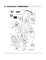
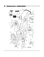
Page 13: ...6 illustrated parts list LBX10151BV 3085656 ...

Page 14: ...Hex GR5 or B 14 3024500 1 DEFLECTOR Side Air 15 91523 4 SCREW 5 16 18 x 5 8 Hex Washer Self Tap 16 46465 1 GUIDE Rope 1 4 20 thread 17 3024501 1 WELDMENT Door Front Side Discharge 18 3031014 1 BUSHING Steel Sleeve 250 ID x 375 OD x 25 Long 19 27223 1 WASHER 1 4 Split Lock 20 91495 1 SCREW 1 4 20 x 3 4 Hex Head Cap GR5 21 3071782 1 SPRING Extension Side Air Discharge Door 22 3031103 1 KNOB Ball Han...

Page 15: ...2 Foam 42 91189 4 BOLT 5 16 18 x 2 Curved Head Square Neck GR2 43 90391 4 WASHER 5 16 Internal Tooth Lock 44 3071800 1 THROTTLE CONTROL Briggs 45 3031220 1 BUSHING Flanged 375 x 500 x 25 625 x 063 Flange 46 90505 1 SCREW 1 4 20 x 2 Hex Head Cap GR5 47 90188 12 WASHER 34 x 69 x 08 Flat 48 76978 1 NUT 1 4 20 Hex Nyloc 49 91298 8 NUT 5 16 18 Hex Nyloc 50 3079209 1 DECAL 10HP B S Intek Briggs P N 2740...

Page 16: ...6 illustrated parts list LBX13151KH 3085657 ...

Page 17: ... 18 Hex GR5 or B 14 3024658 1 DEFLECTOR Side Air 15 91523 2 SCREW 5 16 18 x 5 8 Hex Washer Self Tap 16 46465 1 GUIDE Rope 1 4 20 thread 17 75893 1 DECAL Personal Protection 18 13010 1 DECAL Danger Cut Finger 19 91318 2 SCREW 5 16 18 x 3 4 Hex Head Cap GR5 20 91606 2 NUT 5 16 24 Hex Center Lock 21 29445 2 DECAL GIANT VAC Small 22 75861 1 DECAL GIANT VAC 23 3034053 1 TUBE Front Wheel Extreme 24 9037...

Page 18: ...pper Handle Grip Wide p n 33696 grip 41 74422 1 GRIP 1 0 x 21 1 2 Foam 42 91189 4 BOLT 5 16 18 x 2 Curved Head Square Neck GR2 43 90391 5 WASHER 5 16 Internal Tooth Lock 44 3071799 1 THROTTLE CONTROL Kohler 45 3031813 4 SPACER 375 I D x 750 O D x 5 46 90505 1 SCREW 1 4 20 x 2 Hex Head Cap GR5 47 90188 12 WASHER 34 x 69 x 08 Flat 48 76978 1 NUT 1 4 20 Hex Nyloc 49 91298 8 NUT 5 16 18 Hex Nyloc 50 3...

Page 19: ...6 illustrated parts list LBX85151KH 3085658 ...

Page 20: ...Air 15 91523 4 SCREW 5 16 18 x 5 8 Hex Washer Self Tap 16 46465 1 GUIDE Rope 1 4 20 thread 17 3024501 1 WELDMENT Door Front Side Discharge 18 3031014 1 BUSHING Steel Sleeve 250 ID x 375 OD x 25 Long 19 27223 1 WASHER 1 4 Split Lock 20 91495 1 SCREW 1 4 20 x 3 4 Hex Head Cap GR5 21 3071782 1 SPRING Extension Side Air Discharge Door 22 3031103 1 KNOB Ball Hand Lever 3 8 16 Metal Insert 23 3034053 1 ...

Page 21: ... Curved Head Square Neck GR2 43 90391 4 WASHER 5 16 Internal Tooth Lock 44 3071799 1 THROTTLE CONTROL Kohler 45 3031220 1 BUSHING Flanged 375 x 500 x 25 625 x 063 Flange 46 90505 1 SCREW 1 4 20 x 2 Hex Head Cap GR5 47 90188 12 WASHER 34 x 69 x 08 Flat 48 76978 1 NUT 1 4 20 Hex Nyloc 49 91298 8 NUT 5 16 18 Hex Nyloc 50 3046583 1 DECAL 8 5 HP Extreme 51 75893 1 DECAL Personal Protection 52 13010 1 D...

Page 22: ...6 illustrated parts list LBX9151H 3085659 ...

Page 23: ...r 15 91523 4 SCREW 5 16 18 x 5 8 Hex Washer Self Tap 16 46465 1 GUIDE Rope 1 4 20 thread 17 3024501 1 WELDMENT Door Front Side Discharge 18 3031014 1 BUSHING Steel Sleeve 250 ID x 375 OD x 25 Long 19 27223 1 WASHER 1 4 Split Lock 20 91495 1 SCREW 1 4 20 x 3 4 Hex Head Cap GR5 21 3071782 1 SPRING Extension Side Air Discharge Door 22 3031103 1 KNOB Ball Hand Lever 3 8 16 Metal Insert 23 3034053 1 TU...

Page 24: ...urved Head Square Neck GR2 43 90391 4 WASHER 5 16 Internal Tooth Lock 44 3071798 1 THROTTLE CONTROL Honda 45 3031220 1 BUSHING Flanged 375 x 500 x 25 625 x 063 Flange 46 90505 1 SCREW 1 4 20 x 2 Hex Head Cap GR5 47 90188 12 WASHER 34 x 69 x 08 Flat 48 76978 1 NUT 1 4 20 Hex Nyloc 49 91298 8 NUT 5 16 18 Hex Nyloc 50 3046584 1 DECAL 9 HP Extreme 51 75893 1 DECAL Personal Protection 52 13010 1 DECAL ...

Page 25: ...__________________________________________________________________ __________________________________________________________________________ __________________________________________________________________________ __________________________________________________________________________ __________________________________________________________________________ _________________________________...

Page 26: ...__________________________________________________________________ __________________________________________________________________________ __________________________________________________________________________ __________________________________________________________________________ __________________________________________________________________________ _________________________________...

Page 27: ...__________________________________________________________________ __________________________________________________________________________ __________________________________________________________________________ __________________________________________________________________________ __________________________________________________________________________ _________________________________...

Page 28: ...gation under this warranty is expressly limited to the replacement or repair at an authorized servicing Giant Vac dealer or at a point designated by us of such parts as appear to us to have been defective All defective parts have to be returned freight prepaid before credit will be issued We shall not be liable for transportation charges in connection with the replacement or repair of defective pa...

Reviews: