

www.giadatech.com
Connectors and Jumpers
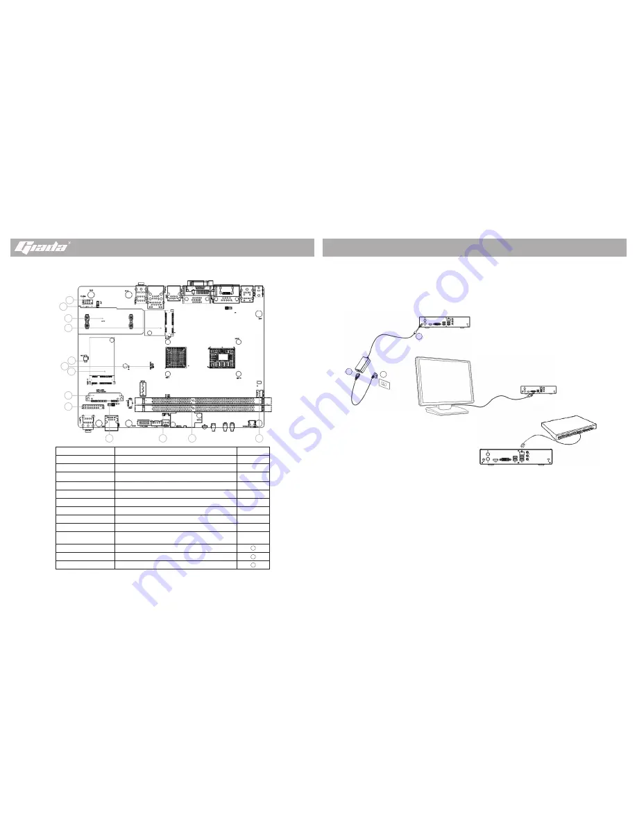
Setting up your computer
This section guides you through connecting the main hardware devices, such as the
adapter, monitor, network device. There are some brief for all kinds of pictures to make
you better understand the basic settings of your computer as below:
After settings are finished securely and tightly, turn your monitor ON and press the power
button on your computer. The Power indicated LED will light and please wait until the
operating system loads automatically.
Note:
Illustrations are for reference only. The ports and their locations, and the chassis
color vary with different models.
Always remove the AC power by unplugging the power cord from the power outlet before
installing or other hardware components.
Before using the product, please verify that all cables and power connectors of your
hardware components are connected.
Description
Usage
Position
F_COM
Connect COM devices
①
JP3
Set the voltage of F_COM(12V /5V,default 5V )
②
HDD support
Fix 2.5” SATA Type HDD
③
M-PCIE
Support PCIE/USB signal
④
BAT
Connect CMOS battery
⑤
M-SATA
Connect MSATA SSD
⑥
CLR_CMOS
Clear CMOS setting
⑦
SATA-HDD
22Pin SATA HDD port
⑧
TPM_Header
Connect TPM module
⑨
HD1X1
Set the voltage of front USB2.0 port
(5VSB or 5V, default 5VSB)
⑩
J5
Set Auto Power ON/OFF
(
default OFF
)
DIMM1/DIMM3
U-DIMM Memory Slot
CPU_FAN
Connect CPU FAN
11
12
13
1
2
3
4
5
6
7
8
9
10
11
12
13
1
3
2
VGA
RJ-45


