


LPPYRA12
- 13 -
V2.5
4.4
LPPYRA12S
CONNECTIONS
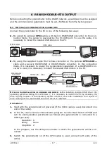
The pyranometer LPPYRA12S has
RS485 Modbus-RTU
output and requires
5…30 Vdc
external power supply. It is to be connected to a power supply and to a
PLC, a data logger or a RS485/USB or RS485/RS232 converter for PC as shown in fig.
4.4. The RS485 output is not isolated.
Connector
Function
Color
1
Power supply negative (GND)
Blue
2
Power supply positive (+Vdc)
Red
3
Not connected
4
RS485 A/-
Brown
5
RS485 B/+
White
6
Housing / Cable shield (SH)
Black
7
Not connected
8
Not connected
Shield
Shield
Lmax = 1200m
B/+
A/-
1
2
3
4
5
6
7
8
B/+
A/-
SGND
+Vdc
GND
GND
+Vdc
A/-
B/+
SH
R
220
T
Ω
R
220
T
Ω
Fig. 4.4: LPPYRA12S connections
Before connecting the pyranometer to the RS485 network, set the address and the
communication parameters, if different from the factory preset (see chapter 6).
Power supply
CPM12-8D… cable
Pyranometer M12
male connector
PLC, data logger or
RS485/USB or
RS485/RS232
converter for PC
Other sensors with
RS485 output
Connect to ground only if it is not possible to
ground locally the housing of the pyranometer


