GHIELMETTI 674.114.913.02 Manual Download Page 11


GHIELMETTI AG –  7UW50 -  Technische Dokumentation 

ROR/09.02.2021 

Page 11 of 19 

Warning : Some of the following test steps carried out in presence of hazardous voltages. The shall 
be performed by qualified personnel only which is thoroughly familiar with all safety regulations and 
precautionary  measures  and  pay  due  attention  to  them.  Non-observance  can  result  in  severe 
personal injury. 

Before initial energization with supply voltage, the relay shall be situated in the operating area for at 
least  two  hours  in  order  to  ensure  temperature  equalization  an  to  avoid  humidity  influences  an 
condensation. 


Check the DC. voltage for the supply of the device, the DC voltage from the trip relays of the 
protection and supervision relays connected to the matrix columns, and the DC voltage for 
all switching elements (breaker coil or master trip relays) connected to the matrix outputs 
(rows) have the same origin and belong to the same DC circuit 


Switch off the circuit breakers for the DC supply 


Fit a DC ammeter in the auxiliary power circuit (range approx.. 1.5A to 3A) 


Close  the  battery  supply  circuit  breaker;  check  polarity  and  magnitude  of  voltage  at  the 
terminals of the unit or at the connector module 


The green LED on the front must come on after at most 0.5s. The unit faulty alarm contact 
of the auxiliary supply circuit must disappear after at most 1s. the current consumption data 
given in the Specifications 


Open the circuit breaker for the DC power supply 


Remove DC ammeter; reconnect the auxiliary voltage leads 


Check through the control wiring from the protection devices 


Check through the tripping circuits to the circuit breakers or to the eternal trip relays 


Check the signal circuits 


Close the battery supply circuit breaker 
 

13


Operating Instructions 

13.1


Safety precautions 

Warning : All safety precautions which apply for work in electrical installations are to be observed 
during tests and commissioning. 

Caution  :  Connection  of  the  device  to  a  battery  charger  without  connected  battery  may  cause 
impermissibly high voltages which damage the device. See also Section 3.1. 1 under Technical data 
for limits. 

13.2


Operation of the device 

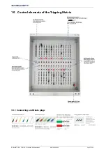
The diode plugs are accessible after removal of the front cap of the unit which can be sealed. The 
diode  plugs  can  be  re-plugged  under  current-free  conditions,  in  accordance  with  the  required 
tripping scheme. 

13.2.1


Marshalling of the trip commands 

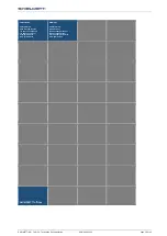
The matrix device comprises 28 inputs (columns) and 10 outputs (rows). Programming is carried out 
by putting a black diode plug into the cross point of a column and row. 

Caution :  Do  not  draw-out  or  insert  a  plug  under  load!  Each  column  can  be  made  effective  by 
inserting the assigned red master plug 

Summary of Contents for 674.114.913.02

Page 1: ...Tripping matrix for Generator Protection Systems GKV 2x11x14 621 SSK 7UW50 250 VDC Part No 674 114 913 02 Manual Edition 04 2020...

Page 2: ...ecting the Tripping Matrix 8 11 1Auxiliary output screw mount connectors 9 12 Installation instruction 10 12 1Unpacking and repacking 10 12 2Preparations 10 12 2 1Mounting and connections 10 12 2 2Che...

Page 3: ...formance at the factory according to the specifications given for the system in this manual However before putting the device into operation we kindly ask you to read this manual and act according to...

Page 4: ...rvicing adjustments maintenance or repair of this product may be performed by qualified personnel only 6 Disclaimer This instruction manual does not purport to cover all details in equipment nor to pr...

Page 5: ...le are used for programming the matrix the reliability being attained by generous over rating with respect to forward current and reverse voltage The diode plugs are inserted from the front and enable...

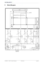
Page 6: ...GHIELMETTI AG 7UW50 Technische Dokumentation ROR 09 02 2021 Page 6 of 19 9 Block Diagram...

Page 7: ...GHIELMETTI AG 7UW50 Technische Dokumentation ROR 09 02 2021 Page 7 of 19 10 Control elements of the Tripping Matrix 10 1 Connecting and Diode plugs...

Page 8: ...GHIELMETTI AG 7UW50 Technische Dokumentation ROR 09 02 2021 Page 8 of 19 11 Interconnecting the Tripping Matrix...

Page 9: ...GHIELMETTI AG 7UW50 Technische Dokumentation ROR 09 02 2021 Page 9 of 19 11 1 Auxiliary output screw mount connectors...

Page 10: ...the relay shall be situated in the operating area for at least two hours in order to ensure temperature equalization and to avoid humidity influences and condensation 12 2 Preparations The operating c...

Page 11: ...t most 0 5s The unit faulty alarm contact of the auxiliary supply circuit must disappear after at most 1s the current consumption data given in the Specifications Open the circuit breaker for the DC p...

Page 12: ...with the operation of thw protected object as well as the rules and regulations switching earthing etc In order to test the tripping circuits a control command must be given from a protection or super...

Page 13: ...of 19 During pushing the RESET button the LEDs on the front will light up thus a LED test is performed at the same time The green LED 15V on the front must be on All terminal screws even those not in...

Page 14: ...GHIELMETTI AG 7UW50 Technische Dokumentation ROR 09 02 2021 Page 14 of 19 14 Dimensions 14 1 Front view...

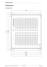
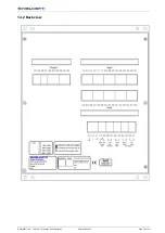
Page 15: ...GHIELMETTI AG 7UW50 Technische Dokumentation ROR 09 02 2021 Page 15 of 19 14 2 Back view...

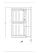
Page 16: ...GHIELMETTI AG 7UW50 Technische Dokumentation ROR 09 02 2021 Page 16 of 19 14 3 Side view...

Page 17: ...ity make break 20 VA Switching voltage 250 VAC DC Permission current 0 1 A 250 VDC Matrix Number of columns inputs 2x14 Number of input indication LED 28 Number of rows outputs 10 Number of output ind...

Page 18: ...ousing cover Warning Hazardous voltages can be present in the device even after disconnection of the supply voltage or after removal of the module from the housing storage capacitors Caution Electrost...

Page 19: ...9 SWITZERLAND GHIELMETTI AG Head Office Switzerland 41 32 671 13 13 Phone 41 32 671 13 14 Fax info ghielmetti ch www ghielmetti ch GERMANY GHIELMETTI AG Office Germany 49 3371 402 754 Phone 49 3371 61...

Reviews: