A x 04
05
06
Page 8 of 10
07
A
10
A x 02
4,0 x 30mm
01
08
INCA 1 DRAWER BEDSIDE CABINET ASSEMBLY INSTRUCTIONS
V1 01/18
Page 1: ...ntents against the parts and fittings check list Do not destroy any of the packaging until you are certain that you have all the necessary parts for the assembly CAUTION There are small compoments use...
Page 2: ...e all the parts listed Ensure that this product is fully assembled as illustrated before use Check all screws or bolts are tightened and inspect regularly This product should only be used on firm leve...
Page 3: ...e product If any components are missing please contact your retailer The fittings pack contains small items that should be kept away from small children 12 11 14 13 15 04 06 10 05 02 07 09 08 03 01 08...
Page 4: ...Front Upright Qty 01 Carton No 1 1 Size 415x45x16mm Description 13 Left Drawer Side Qty 01 Carton No 1 1 Size 270x92x13mm Description 05 Left Front Upright Qty 01 Carton No 1 1 Size 415x45x16mm Descri...
Page 5: ...04x B D26x20mm 16x C Wood Dowel D8x30mm 30x A CSK Screw D4x30mm CSK Screw 10x F Nail Pin L 23mm Fixings not to scale Page 5 of 10 Fixings to scale 01x D D35x30mm 04x G L100mm INCA 1 DRAWER BEDSIDE CA...
Page 6: ...02 Page 6 of 10 C x 16 G x 04 8 0 x 30mm C C C C C C C C C C C C C G G G G 08 2x 02 03 C 06 13 15 A A A A 03 02 04 05 A A x 04 4 0 x 30mm INCA 1 DRAWER BEDSIDE CABINET ASSEMBLY INSTRUCTIONS V1 01 18 G...
Page 7: ...03 04 Page 7 of 10 A A A A 02 03 06 A x 04 4 0 x 30mm A A A 09 A A 09 A x 04 4 0 x 30mm INCA 1 DRAWER BEDSIDE CABINET ASSEMBLY INSTRUCTIONS V1 01 18...
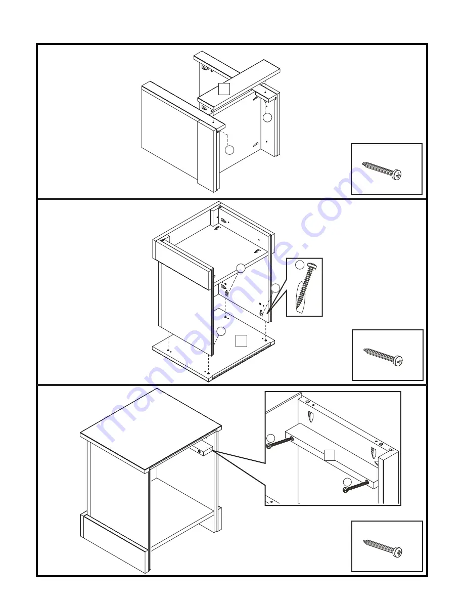
Page 8: ...A x 04 A x 04 05 06 Page 8 of 10 07 A A 10 A x 02 4 0 x 30mm A A A A 01 A A 08 4 0 x 30mm 4 0 x 30mm INCA 1 DRAWER BEDSIDE CABINET ASSEMBLY INSTRUCTIONS V1 01 18...
Page 9: ...04 D x 01 E x 01 A x 08 08 09 Page 9 of 10 10 F F F F F F F F 07 F F F F F 07 F x 10 14 A E D A A A 11 12 A A 13 15 A E D 4 0 x 30mm B B B B INCA 1 DRAWER BEDSIDE CABINET ASSEMBLY INSTRUCTIONS V1 01...
Page 10: ...cally check to ensure that the components are in their proper position free from damage Also make sure the connectors are tight and secure COMPLETE ASSEMBLY Keep instructions for future reference Page...
Page 11: ...s against the parts and fittings check list Do not destroy any of the packaging until you are certain that you have all the necessary parts for the assembly CAUTION There are small compoments used in...
Page 12: ...en Make sure the legs remain in contact with the ground Tools not included WARNINGS DO NOT use power tools to construct this product DO NOT tighten screws until fully assembled DO NOT over tighten scr...
Page 13: ...the product If any components are missing please contact your retailer The fittings pack contains small items that should be kept away from small children INCA 2 DOORS WARDROBE ASSEMBLY INSTRUCTIONS 0...
Page 14: ...nt Upright Qty 01 Carton No 1 1 Size 1735x45x16mm Description 13 Right Door Qty 01 Carton No 1 1 Size 1640x323x16mm Description 05 Left Front Upright Qty 01 Carton No 1 1 Size 1735x45x16mm Description...
Page 15: ...Screw D3 0x14mm CSK Screw 02x J Truss Head Screw D4 7x16mm 02x I D26x20mm 3 02x P D15mm 22x A Wood Dowel D8x30mm 06x B CSK Screw D4 0x40mm 31x D CSK Screw D4x30mm CSK Screw 40x F Nail Pin L 23mm 01x...
Page 16: ...03 K K K K K K K K D A A A D D D D D D A A A A A A A D D D D D D D 07 04 05 03 02 08 06 D A A D A A D A 07 L C C C B x 06 4 0 x 40mm Ax 22 8 0 x 30mm C x 06 3 0 x 14mm D x 23 4 0 x 30mm K x 08 Lx 02 0...
Page 17: ...D D D 09 10 D D D D D 09 09 10 08 C C E C C C G J 13 M M M M 12 16 D D D M x 04 D x 08 4 0 x 30mm E x 06 G x 02 J x 2 C x 36 3 0 x 14mm 3 5 x 20mm 02 Page 7 of 10 INCA 2 DOORS WARDROBE ASSEMBLY INSTR...
Page 18: ...4 15 14 14 Ha Ha Hb Ha Ha Hb I I 13 12 07 11 06 C Ha I 03 Page 8 of 10 INCA 2 DOORS WARDROBE ASSEMBLY INSTRUCTIONS F x 40 I x 2 Ha H x 04 Hb C x 16 3 0 x 14mm V1 01 18 Hb C C C Ha C C C Ha C C C Ha Hb...
Page 19: ...e wall using the wall strap The screw to fix to the wall is not supplied with this product Please use screw and fixing appropriate for the wall type If in doubt you should seek professional advice Alw...
Page 20: ...cally check to ensure that the components are in their proper position free from damage Also make sure the connectors are tight and secure COMPLETE ASSEMBLY Keep instructions for future reference Page...
Page 21: ...s against the parts and fittings check list Do not destroy any of the packaging until you are certain that you have all the necessary parts for the assembly CAUTION There are small compoments used in...
Page 22: ...level ground Keep small parts out of reach of children Make sure the legs remain in contact with the ground Tools not included WARNINGS DO NOT use power tools to construct this product DO NOT tighten...
Page 23: ...t If any components are missing please contact your retailer The fittings pack contains small items that should be kept away from small children 12 x 3 16 14 13 15 11 11 02 03 09 01 10 06 04 05 09 08...
Page 24: ...ide Qty 03 Carton No 1 1 Size 290x115x13mm Description 05 Left Front Upright Qty 01 Carton No 1 1 Size 700x45x16mm Description 14 Drawer Back Qty 03 Carton No 1 1 Size 525x115x13mm Description 06 Bott...
Page 25: ...Wood Dowel D8x30mm 56x A CSK Screw D4x30mm CSK Screw 20x F Nail Pin L 23mm 01x H CSK Screw D3 5x14mm CSK Screw Fixings not to scale Page 5 of 11 Fixings to scale 01x I L 150mm Safet Strap 06x D D35x3...
Page 26: ...3 C x 24 G x 04 A x 06 A A A A A 02 05 04 03 A A A x 04 A A 06 02 03 A A 07 A 4 0 x 30mm 4 0 x 30mm 8 0 x 30mm INCA 3 DRAWERS CHEST ASSEMBLY INSTRUCTIONS V1 01 18 G G G G C 02 03 C C C C C x 6 08 C C...
Page 27: ...A x 04 04 05 Page 7 of 11 06 A x 04 A A A 09 A 09 A A x 02 A A 10 A A A A 01 4 0 x 30mm 4 0 x 30mm 4 0 x 30mm INCA 3 DRAWERS CHEST ASSEMBLY INSTRUCTIONS V1 01 18...
Page 28: ...f 11 A A A A A A 08 08 08 08 08 A A 08 08 A A A A x 24 C x 12 E x 06 D x 06 3x A 13 15 C C C C 12 15 13 A A A 16 E E 14 A D D A A A E D 4 0 x 30mm 4 0 x 30mm 8 0 x 30mm INCA 3 DRAWERS CHEST ASSEMBLY I...
Page 29: ...B x 04 F x 20 09 10 Page 9 of 11 F F F F F F F F F F F F F F F F F F F F F F F 11 11 11 11 11 17 17 B B B B INCA 3 DRAWERS CHEST ASSEMBLY INSTRUCTIONS V1 01 18...
Page 30: ...x to the wall is not supplied with this product Please use screw and fixing appropriate for the wall type If in doubt you should seek professional advice Always ensure the area to be Warning drilled i...
Page 31: ...cally check to ensure that the components are in their proper position free from damage Also make sure the connectors are tight and secure COMPLETE ASSEMBLY Keep instructions for future reference Page...