background image


10 


Installation 

The following descriptions refer to a door which is not further defined. The door 
manufacturer's specifications must also be observed. 


Warning – Injury or danger to life possible! 


Use a lifting device with sufficient load-carrying capacity for installation tasks. 


Completely grease the door shaft. 


BAGAE03003_Z002


Mount the key. 


BAGAE03004_Z001


Summary of Contents for 10005218 10012

Page 1: ...f Installation Instructions ELEKTROMAT SI 260 5 80 00 Model 10005218 10012 en Status 26 03 2021 ...

Page 2: ...2 GfA ELEKTROMATEN GmbH Co KG Wiesenstraße 81 D 40549 Düsseldorf www gfa elektromaten de info gfa elektromaten de ...

Page 3: ...ection 14 9 Limit switch connection 15 10 Emergency manual operation hand chain operator 16 11 Completion of commissioning testing 18 12 Declaration of incorporation Declaration of conformity 21 Symbols Warning Potential injury or danger to life Warning Danger to life from electric current Note Important information Requirement Required action Schematic representations are based on product example...

Page 4: ...ing of door systems Expert knowledge relevant skills and practical experience are what set apart qualified persons They are capable of safely carrying out the tasks involving installation maintenance and modernisation according to the instructions Safe operation The safe operation of the product can only be ensured if it is used as specified Follow the installation instructions Observe all specifi...

Page 5: ... third parties Warning Danger from improper use of the product Do not let children operate the product unsupervised or use as a toy Warning Danger to life from incorrect installation Work carried out improperly may result in death or severe injury from electrical current or falling parts Allow only competent people to carry out the work Disconnect all cables from the power supply Observe valid reg...

Page 6: ... rpm Supply voltage 3 400 V Operating current 3 90 A Operating frequency 50 Hz Power factor cos φ 0 76 Maximum movement per hour 6 h 1 Hand forces 182 N Class of protection IP 65 Limit switch range maximum revolutions of output shaft hollow shaft 10 Braking torque spring loaded brake 100 Nm Braking voltage 103 130 V DC Rectifier type EGR 230 103 Temperature range 10 40 60 C 1 When using a temperat...

Page 7: ...ocking torque and the approval number of the safety brake are available in the technical data of these instructions Warning Danger of the door dropping If you need to apply more than the permissible force of 390N according to DIN EN 12604 DIN EN 12453 to move the door by emergency manual operation this indicates a stalling on the drive unit or door Releasing the stalling may cause the door to drop...

Page 8: ...even for maximum holding or locking torque observe technical data Connection elements Use self locking connection elements with a minimum strength of 800 N mm2 8 8 Use a screw that precisely fits the hole Use adequately dimensioned washers for elongated holes BAGAB00002_Z002 BAGAB00003_Z002 3 1 Permissible mounting positions BAGAC07001_Z003 ...

Page 9: ...les are provided for mounting Installation is only permitted with an additional torque mount Ⓑ Warning Injury or danger to life possible Check installation aid Ⓐ before each use and replace it in case of damage BAGAD07001_Z003 ...

Page 10: ...ther defined The door manufacturer s specifications must also be observed Warning Injury or danger to life possible Use a lifting device with sufficient load carrying capacity for installation tasks Completely grease the door shaft BAGAE03003_Z002 Mount the key BAGAE03004_Z001 ...

Page 11: ...7003_Z001 Remove transport protection BAGAE07004_Z002 Tighten all connection elements M20 with a torque of 380 Nm Install all further connection elements according to the specifications of the door manufacturer BAGAE07005_Z002 380 Nm ...

Page 12: ...s are de energised Observe the applicable regulations and standards Make a proper electrical connection Use suitable tools Performing electrical installation Remove the cover Insert the motor plug Insert the limit switch plug BAHAC13_Z001 Completing the electrical installation Mount the cable entries and or cable glands ...

Page 13: ...13 6 Limit switch adjustment The adjustment of the final limit positions OPEN and CLOSE is described in the instructions for the door control panel ...

Page 14: ...14 7 Motor connection G1 Rectifier EGR M1 Motor X13 Motor plug Y1 Spring applied brake 8 Alternative motor connection G1 Rectifier EGR M1 Motor X13 Motor plug Y1 Spring applied brake ...

Page 15: ...15 9 Limit switch connection F10 Thermal contact S10 Emergency manual operation X12 DES connection 1 Safety circuit 2 Channel B RS485 3 Ground 4 Channel A RS485 5 Safety circuit 6 Supply voltage ...

Page 16: ...ncy manual operation must be carried out against the closed brake Warning Danger of the door dropping If you need to apply more than the permissible force of 390N according to DIN EN 12604 DIN EN 12453 to move the door by emergency manual operation this indicates a stalling on the drive unit or door Releasing the stalling may cause the door to drop Adopt a secure position For drive units with brak...

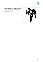
Page 17: ...17 Switch on by pulling the red handle Open or close by pulling the chain Switch off by pulling the green handle ...

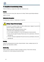
Page 18: ...ng The gearbox stalls Releasing the stalling may cause the door to drop Block the door for pedestrians and vehicles Do not release the stalling Do not use the emergency manual operation Secure the door against dropping Please observe the specifications of the door manufacturer The drive unit needs replacement Please observe the specifications of the door manufacturer Mounting Check all mounting el...

Page 19: ... its equipment The manufacturer s specifications must be observed The brake release for doors without counter balancing may only be used in the CLOSE final limit position Warning Injury or danger to life possible Service life of the brake replacement of the entire brake in the case of Operation with mains supply after 250 000 door cycles Operation with frequency inverter after 1 000 000 door cycle...

Page 20: ...20 Entire drive unit Note Have the drive checked annually by a specialist Shorter inspection interval for frequently used doors Observe the applicable regulations and standards ...

Page 21: ... complies with the provisions of the above mentioned directives Authorised representative to compile the technical documents is the undersigned Düsseldorf 10 08 2018 Stephan Kleine CEO Signature The following requirements from Appendix I of the Machinery Directive 2006 42 EC are met 1 1 2 1 1 3 1 1 5 1 2 2 1 2 3 1 2 6 1 3 2 1 3 3 1 3 9 1 5 1 1 5 2 1 5 4 1 5 6 1 5 7 1 5 8 1 5 9 1 5 10 1 5 11 1 5 13...

Page 22: ...22 ...

Page 23: ...23 ...

Page 24: ...24 ...

Reviews: