Manual hook bolt lock, Lock M
EN Installation instructions
161911-01
Page 1: ...Manual hook bolt lock Lock M EN Installation instructions 161911 01 ...
Page 2: ...Inspection of the installed system 4 1 5 Environmentally conscious working 4 2 Overview 5 2 1 Diagrams 5 2 2 Tools and aids 5 2 3 Torques 5 3 Installation 6 3 1 Installing hook bolt lock Lock M in the main closing edge 6 3 2 Installing the strike plate in the main closing edge or post profile 8 3 3 Post installation 1 leaf 9 4 Service and maintenance 13 5 Troubleshooting 13 ...
Page 3: ...ion maintenance and repair work must be performed by properly trained personnel authorised by GEZE à à The country specific laws and regulations are to be observed during safety related tests à à If unauthorised changes are made to the system GEZE cannot be held liable in any way whatsoever for any resulting damage and the approval for use in escape and rescue routes ceases à à GEZE makes no guara...
Page 4: ... end ferrules for wire cores à à Attach safety stickers to glass leaves à à Danger of injury with opened drive Hair clothing cables etc can be drawn in by rotating parts à à Danger of injury caused by unsecured crushing impact drawing in or shearing spots à à Danger of injury due to broken glass à à Danger of injury due to sharp edges in the drive à à Danger of injury during installation through f...
Page 5: ...715 9 9873 70715 9 9874 Leaf drawing PL 70715 9 9877 70715 9 9878 Leaf drawing SLT 70487 ep 10 70717 ep 08 ep 09 Installation diagrams SLT 70504 ep 21 ep 22 Installation diagrams EC 70506 ep 19 ep 20 Installation diagrams PL 70511 ep 18 ep 19 Installation diagrams SL NT 2 2 Tools and aids Tool Size Remark Tape measure Marking pen Torque spanner Blind rivet nut tool M5 Allen key 1 5 mm 2 mm 2 5 mm ...
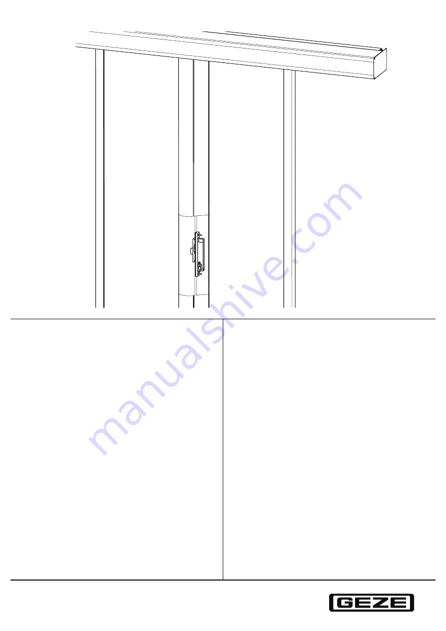
Page 6: ...bolt lock Lock M in the main closing edge 3 1 1 Installing hook bolt lock Lock M in the main closing edge without pushing rosette Blind rivet nut M5 flat head caulk steel X X Heed the installation and care instructions from the respective manufacturer of the lock cylinder used X X The lock cylinder must be provided on site M5 x 30 SW3 3 Nm M5 x 35 SW3 3 Nm ...
Page 7: ...M in the main closing edge with pushing rosette Blind rivet nut M5 flat head caulk steel X X Heed the installation and care instructions from the respective manufacturer of the lock cylinder used X X The lock cylinder must be provided on site M5 x 35 SW3 3 Nm M5 x 30 SW3 3 Nm ...
Page 8: ...dge or post profile X X Screw the M5 screw 2 into the strike plate 1 X X Thread the strike plate 1 with M5 screw into the main closing edge of the moving leaf 2 leaf or post profile 1 leaf X X Screw in two screws with countersunk head 3 and tighten X X Undo the screw 2 again M5 x 16 SW3 3 Nm ...
Page 9: ...ght closing The illustrations below show the version 1 leaf right closing Implementation of the 1 leaf left closing version is reversed accordingly X X Adjust the position of the door leaf 1 Heed safe distances to the light barrier profile side part and floor X X Use 2 screws 3 to fix the square post 2 provisionally at the top and bottom ...
Page 10: ...sary The fixing and underlay material must be provided on site X X Unscrew the side screen profile 4 X X Mount the square post 2 with screws 3 on the wall X X Mount the side screen profile 4 with screws 5 on the square post 2 X X Adjust the vertical position in relation to the door leaf X X Adjust the position of the L angle 6 as cover blind and mark drill holes X X Drill the holes with a Ø 2 75 m...
Page 11: ...post to 4 mm below the side screen profile leaf 8 3 3 2 1 leaf system in front of a continuous wall right or left closing X X Adjust the position of the door leaf 1 Heed safe distances to the light barrier profile side part and floor X X Adjust the position of the side screen profile 2 and wall rail 3 in relation to the door leaf 1 and mark on the wall 4 mm ...
Page 12: ...ook bolt lock Lock M 12 Installation X X Mount the wall profile 3 with screws 4 on the wall underlay if necessary X X Screw the side screen profile 2 with screws 5 through the wall profile 3 on the wall ...
Page 13: ...or flashes in the display X X Service and maintenance should then be carried out promptly Test spot Action Comments Screws X X Check for tight fit X X Tighten the screws if necessary Lock X X Check manually for function and smooth running X X Replace components if necessary X X Disassemble locking if necessary check for soiling and damage 5 Troubleshooting Cause of fault Remedy Hook bolt lock stif...
Page 14: ...Hook bolt lock Lock M 14 Troubleshooting ...
Page 15: ...Hook bolt lock Lock M 15 ...
Page 16: ...com cn France GEZE France S A R L E Mail france fr geze com www geze fr Hungary GEZE Hungary Kft E Mail office hungary geze com www geze hu Iberia GEZE Iberia S R L E Mail info geze es www geze es India GEZE India Private Ltd E Mail office india geze com www geze in Italy GEZE Italia S r l E Mail italia it geze com www geze it GEZE Engineering Roma S r l E Mail roma geze biz www geze it Poland GEZ...