187132-00_GCVR300TouchT_für IO-Box_Montageanleitung_20200514
1
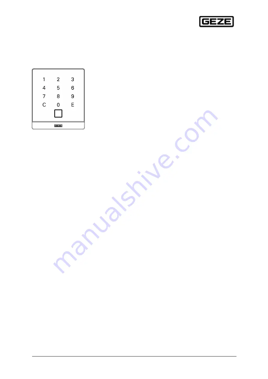
GCVR 300 Touch T für I/O BoxGCVR 300 Touch T for I/O Box
DE Montage- und InstallationsanleitungEN Assembly and Installation Instructions
Page 1: ...187132 00_GCVR300TouchT_für IO Box_Montageanleitung_20200514 1 GCVR 300 Touch T für I O Box GCVR 300 Touch T for I O Box DE Montage und Installationsanleitung EN Assembly and Installation Instructions ...
Page 2: ...3 Safety Instructions 4 4 Lieferumfang 4 4 Scope of delivery 4 5 Produktbeschreibung 4 5 Product description 4 6 Montage und Anschluss 5 6 Mounting and Installation 5 7 Inbetriebnahme 10 7 Installation 10 7 1 Beschreibung der LED Funktionen 11 7 1 Description of the LED functions 11 8 Technische Daten 12 8 Technical data 12 9 Generelle Informationen 12 9 General information 12 10 Pflegehinweise 14...
Page 3: ...Informationen Produktinformationen und bestimmungsgemäße Ver wendung Fehlgebrauch Produktleistung Produktwartung Informations und Instruktionspflichten zu beachten Die Nichtbeachtung entbindet den Hersteller von seiner Haftungspflicht Bei Kombination mit Fremdgeräten übernimmt GEZE keine Gewährleistung In accordance with the manufacturer s liability for its products as defined in the Product Liabi...
Page 4: ...0815 must be observed when laying the cables 4 Lieferumfang 4 Scope of delivery GEZE GVR 300 Touch T für I O Box ID 187108 187122 je nach bestellter Ausführung siehe Typenschild GEZE GVR 300 Touch T für I O Box Montage und Installationsanleitung GEZE GVR 300 Touch T for I O Box ID 187108 187122 depending on the version ordered see type label GEZE GVR 300 Touch T for I O Box assembly and installati...
Page 5: ...r sonstigen elektrotechnischen Fachkraft Die urheber rechtlichen Bestimmungen sind zu beachten The drawings were created with the greatest possible care and correspond to the state of development planning and knowledge of the drawing date or the last change made Use at your own risk since processing adding or leaving out other relevant order in formation in particular can result in a completely di...
Page 6: ...terputzvariante Flush mounted variant Wandhalterung mittels den mitgelieferten Schrauben auf eine DIN Geätedose mit Geräteschrauben abstand 60mm schrauben Fix the wall mount on a standard flush mounted box with screw distance 60 mm by the help of the provided screws ...
Page 7: ...unt variant Zuführung des Anschlusskabels entweder oben unten oder direkt aus der Wand Rückwand mittels geeigneten Schrauben an die Wand schrauben Entry of the connecting cable either on top below or directly from the wall Fix the surface frame on the wall by the help of appropriate screws ...
Page 8: ...de from the wall The wall mount must always lay totally flat on the wall or the individual mounting surface In general the wall or the individual mounting surface must be flat and level so that the wall mount always lays flat on it Montage der Wandhalterung auf Standard Unterputzdose Hohlraumdose oder direkt auf der Wand Installing of the wall mount on a standard flush mounted box cavity wall sock...
Page 9: ...cken 2 Lesemodul plan auf die Wandhalterung oder auf das Aufputzgehäuse aufsetzen dabei das Anschlusskabel mit dem Lesemodul in die UP Dose oder in das AP Gehäuse zurückschie ben 3 Das aufgesetze Lesemodul nach unten schie ben bis das Lesemodul auf der Wandhalte rung oder dem AP Gehäuse einrastet 4 Nach dem erfolgreichen Einrasten Verriege lungsleiste in das Lesemodul einschieben bis sie ebenfalls...
Page 10: ...eased Pull the unlocked locking bar out forwards and remove it from the reader module 2 Push the reader module upwards snap out Pull the reader module out forwards from the wall mount or the surface frame 7 Inbetriebnahme 7 Installation Die erfolgreiche Bereitschaft des Systems wird nach Anschluss der Spannungsversorgung am GCVR 300 Touch T RFID Leser durch das dauerhafte gelbe Leuchten der mittle...
Page 11: ...ity blinkt schnell flashes fast INT Systeminitialisierung unter angelegter Spannung System initialization under voltage Betrieb Grundzustand Operation basic state System betriebsbereit Warten auf Aktion System ready Waiting for action Freigabe Release Freigabe über Relais erfolgt Release via relay leuchtet lang shines long Keine Freigabe No release Unberechtigtes Identmedium PIN falsch Unauthorize...
Page 12: ...mperatur C 25 C bis 60 C 25 C to 60 C Schutzart IP Protection class Frontseitig in montiertem Zustand IP 54 Die Abdichtung gegen die Montagewand be stimmt die maximal erreichbare Schutzart IP 54 Front panel in assembled condition IP 54 The sealing against the mounting wall determines the maximum attainable protection class IP 54 9 Generelle Informationen 9 General information Lesedistanz Reading d...
Page 13: ... Dieser Punkt ist vor allem bei der Installation der Leserkomponenten in Metallfrontplatten auch Metallsäulen usw relevant Metal in the active effective area of the HF field The transmission energy is steamed This point is particularly relevant when installing the reader components in metal front panels including metal columns etc Störbeeinflussung Interference Die Leser können sich gegenseitig st...
Page 14: ...ders especially over long distances ensure that the cable cross section is suffi cient Since the current consumption of the individual systems is partly pulsed short term voltage drops cannot be detected with a conventional multimeter digital or analog However these voltage drops can cause a POWER ON RESET on the reader component which can lead to communication prob lemsWhen dimensioning the volta...