

Set up wireless connection
X
Slide a free wireless device switch SW1x of the wireless module GC 171 to the ON position.
The corresponding wireless device LED1x starts to flash green. If a connection has already
been set up for the wireless device switch selected, this is overwritten by the following pro-
cess. The wireless module GC 171 waits for the connection query for a new wireless device.
If a new wireless device does not respond within 2 minutes, the wireless module GC 171
cancels the connection attempt, the corresponding wireless device LED1x lights up red.
X
To start the connection attempt again, slide the corresponding wireless device switch
SW1x to the OFF position briefly, then slide it back into the ON position.
The corresponding wireless device LED1x now flashes green again for 2 minutes.
LED1x
SW1x
Install batteries
X
Remove the protective films from the battery compartment (4) of the new wireless detec-
tor and install the batteries (5) in the new wireless detector. Make sure of correct polarity.
The LED (2) on the new wireless ceiling-mounted detector flashes green twice first, then
lights up orange for one second and then flashes red four times.
As soon as the LED (2) goes out after that, the connection can be set up.
2
X
Slide the set-up switch (6) on the new wireless detector to the 1 position.
After a short time, the LED of the new wireless detector will flash green for a few seconds.
The corresponding wireless device LED1x of the wireless module GC 171 lights up green
permanently.
If the LED (2) on the new wireless detector lights up red permanently, no connection has
been made.
X
In this case, remove the batteries from the new wireless detector, slide the set-up
switch (6) on the new wireless detector back and forward six times and install the bat-
teries (5) again. Continue as described above.
X
Fit the wireless ceiling-mounted smoke detector to the base (8).
X
Slide the wireless device switch SW1x of the wireless module GC 171 to the OFF
position again.
The colour the corresponding wireless device LED1x flashes indicates the quality of
the wireless connection (see connection quality).
X
Optimise the quality of the wireless connection if necessary by changing the
position of the wireless detector.
LED1x
SW1x
The connection of the wireless module GC 171 to the new wireless detector has been set up.
X
Note the set-up connection (the number of the assigned wireless device switch)
onto the identification plate of the new wireless detector.
X
To set up further wireless connections, continue with step “Set up wireless connection”.
X
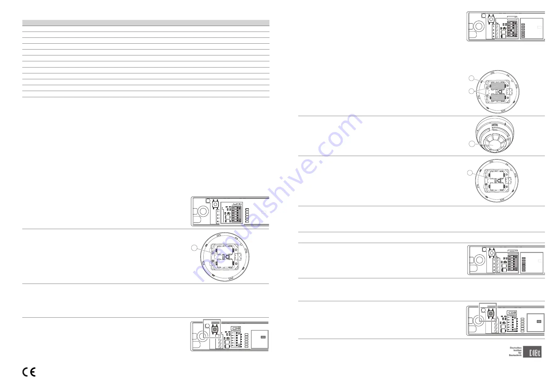
Press the PB1 push button on the wireless module GC 171 briefly to change to the
“operating” mode.
The status LED2 of the wireless module GC 171 goes off.
1
2
3
4
KL1
SW1
LED1
24V
GND
MRB
AS
1
2
3
4
LED2
PB1
SW2
GC161
GC151
KL1
SW1
LED1
24V
GND
MRB
AS
1
2
3
4
LED2
PB1
SW2
GC161
GC151
EN 54-7*
EN 54-25*
EN 14637**
*
EN 54-7 and EN 54-25 certified by BRE Global Ireland only with the GC171_L gateway (see document L20-GC171_-0001_REV_A.1).
**
EN 14637 certified by KRIWAN with GC 172, GC 173, GC 175 and GC171 gateway.
3.4 Signalling
State, event
LED for displaying state
Switch on
lights up green for 1 s, then repeated red
Start set-up of the wireless connection
flashes green until the wireless connection is established
Fault during set-up of the wireless connection
lights up red
Operation
off
Alarm
flashes red (0.5 s on – 0.5 s off)
Battery 1 discharged
flashes orange (0.1 s on – 5 s off)
Battery 2 discharged
flashes green (0.1 s on – 5 s off)
Both batteries discharged
flashes orange/green alternately (0.1 s on – 5 s off)
Other faults
flashes orange/green alternately (0.5 s each)
Manipulation
off
Loss of connection
off
Test mode – the detector reacts sensitively to aerosol pulses
flashes green every second for 1 minute
3.5 Battery replacement
The wireless detector signals “low battery charge” to the wireless module GC 171 if the charge state of the batteries is no longer
sufficient. Both batteries (5) always have to be replaced together. The set-up switch (6) for the wireless detector must not be activated.
X
Take the wireless detector out of the base (8).
X
Remove the battery compartment cover (3).
X
Remove both batteries (5).
X
Insert new batteries (type CR123A) – make sure polarity is correct.
X
Replace the battery compartment cover (3).
X
Insert the wireless detector into the base (8).
X
Test the wireless detector. It can take up to a minute for the wireless detector to be ready for operation after
battery replacement.
3.6 Connecting the wireless ceiling-mounted smoke detector GC 172 to wireless module GC 171
A maximum of 6 wireless connections can be set up at one wireless module GC 171.
Pre-conditions
ú
All the wireless device switches of the wireless module GC 171 are in the OFF position.
SW1x
ú
The set-up switch (6) of the new wireless detector is set to the ON position.
ú
The protective films are on the battery compartment of the new wireless detector
and the batteries for the new wireless detector have not been fitted.
Set up a new wireless connection
X
Switch the supply voltage for the wireless module GC 171 on.
The wireless module is in “operating” mode.
X
Press the PB1 push button on the wireless module GC 171 briefly to change to the “set
up wireless connection” mode. The status LED2 of the wireless module GC 171 now
lights up red permanently.
1
2
3
4
KL1
SW1
LED1
24V
GND
MRB
AS
1
2
3
4
LED2
PB1
SW2
GC161
GC151
KL1
SW1
LED1
24V
GND
MRB
AS
1
2
3
4
LED2
PB1
SW2
GC161
GC151
GEZE GmbH hereby declares that the components of the wireless kit for hold-open systems complies with the Directives
2014/53/EU and 2011/65/EU. The complete text of the EU Declaration of Conformity, and the Declaration of Performance, is
available at the following internet address: www.geze.com


