


26
- Select PRIVACY using the UP or DOWN button and
press the MENU button to activate the PRIVACY option.
1) AREA
: To specify the PRIVACY area
- Select AREA using the UP or DOWN button. You can
select area from 1~4 position using the LEFT or RIGHT
button.
1
2
3
4
2) DISPLAY
: To display the PRIVACY Zone area
- Select DISPLAY using the UP or DOWN button. You can
select between ON/OFF using the LEFT or RIGHT button.
(1) ON : display the PRIVACY Zone area
(2) OFF : disable
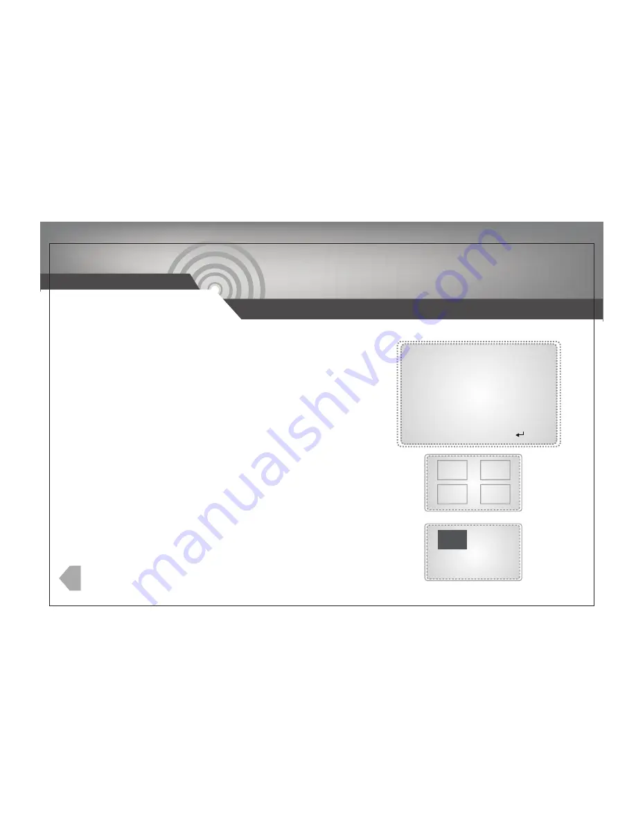
PRIVACY
AREA
DISPLAY
COLOR
TOP
BOTTOM
LEFT
RIGHT
INITIAL
RETURN
1
OFF
WHITE
15
31
44
104
ON
3) COLOR
: To change color of PRIVACY zone
- Select COLOR using the UP or DOWN button. You can
adjust from WHITE, YELLOW, GREEN, BLUE, RED, BLACK,
or GRAY using the LEFT or RIGHT button.
6. PRIVACY
:
IR DOME CAMERA


