

G-Cam/EFD-2251 Full HD IR Dome IP Camera Quick Guide
This guide is for quick installing and connecting the G-Cam/EFD-2251 in-ceiling IP camera. For more details, please
refer to the User’s Manual in the supplied CD.
Camera’s Connectors
Nr.
Connector
Pin
Definition
Remarks
1
RJ-45
For network and PoE connections
2
Not in use
1
X
2
X
Alarm & Audio I/O*
3
Alarm Out −
Alarm connection
4
Alarm Out +
5
Alarm In −
6
Alarm In +
7
Audio Out
Audio Out
8
GND
common ground audio
9
Audio In
Audio In
Power (DC 12V)
10
12 VDC −
Power connection
11
12 VDC +
3
CDS light sensor
-
4
MikroSD-Kartenslot
-
Insert the microSD card into the card slot to store videos and snapshots.
Do not remove the microSD card when the camera is powered on.
5
Default-Taster
-
Press the default button with a proper tool for at least 20 seconds to restore
the camera.
*
Listen only is supported by GEUTEBRÜCK DVRs!
**Do
NOT
connect external power supply to the alarm I/O connector of the IP camera.
NOTE:
It is not recommended to record with the microSD card for 24/7 continuously, as it may not be able to
support long term continuous data read/write. Please contact the manufacturer of the microSD card for
information regarding the reliability and the life expectancy.
Camera Cabling
Please follow the instructions below for cable connections and configuration.
Power Connection
Please use a DC 12V power adaptor and plug it to the camera and the power outlet. Alternatively, connect the ethernet
cable to the camera’s RJ-45 port and plug the other end of the cable into a PoE switch (IEEE 802.3af, 15.4 W).
NOTE:
If PoE is used, make sure PSE is in used in the network.
Ethernet Cable Connection
Connect one end of the Ethernet cable to the RJ-45 connector of the camera, and plug the other end of the cable to
the network switch or PC.
NOTE:
In some cases, Ethernet crossover cable might be needed when connecting the camera directly to the
PC.
Green Link Light indicates good network connection.
Orange Activity Light flashes for network activity indication.
Set up network environment
Be sure that the device and PC are on a same area network before running the installation.
User name:
root
Password:
admin
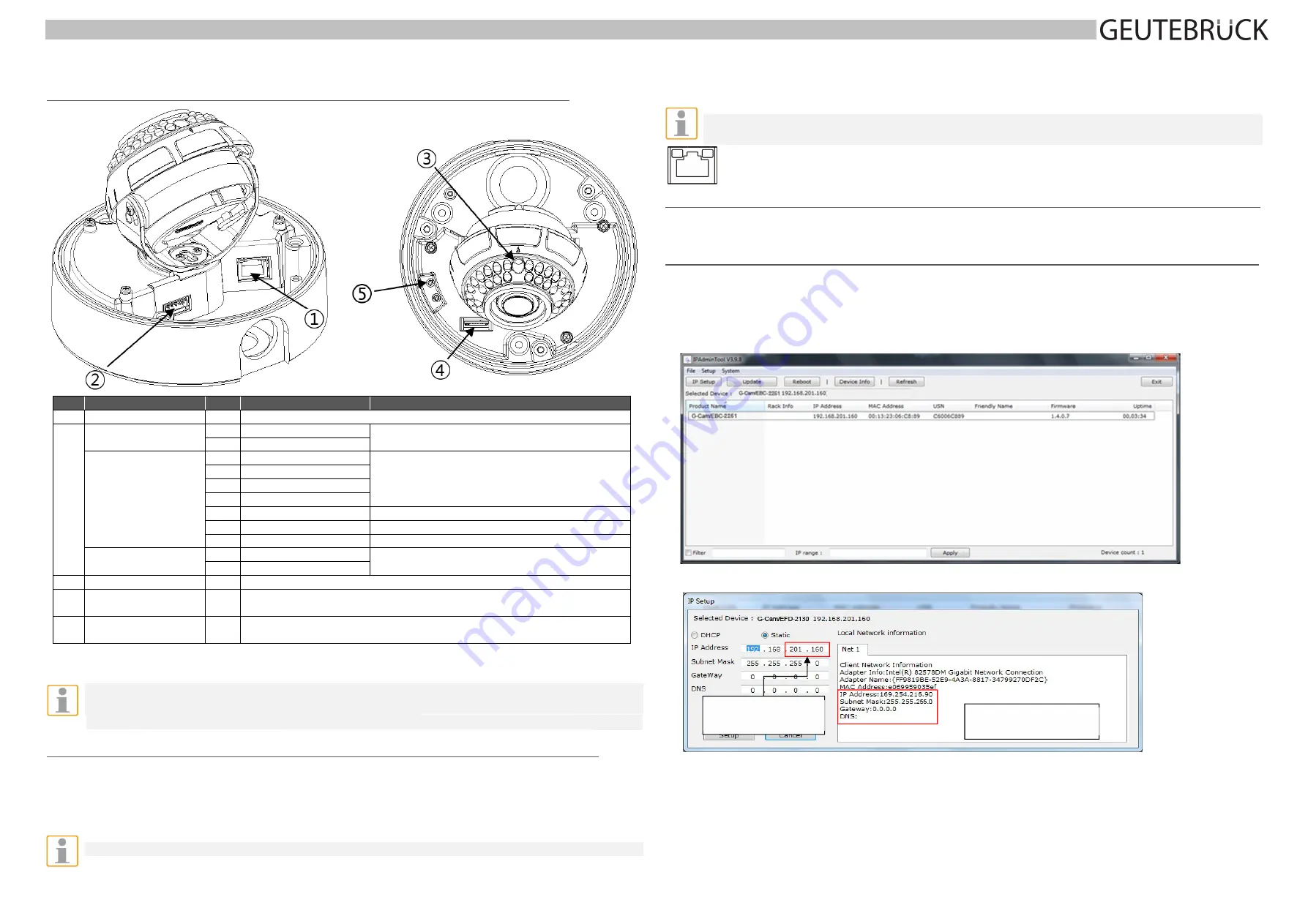
Custom IP Environment
IPAdminTool
is provided on attached CDRom.
IPAdminTool
is a management tool, which automatically scans all of the network products for users to perform
administrative tasks, which includes network configurations, firmware update, device reboot, and device organizations.
To modify the device’s default IP address for customized network area:
1.
Find the device from the IPAdminTool’s list and highlight the device’s name.
2.
Right-click the mouse and select “IP Address”; IP Setup window appears.
3.
In the IP Setup’s window, information under ‘Local Network information’ displays the user/PC’s network area
information. Those information need to be incorporated to the IP Address, Subnet Mask, Gateway, and DNS boxes,
except the last 2 sets of IP Address, which are to be the unique numbers for the device. Refer to the image above for
the setting
4.
Click ‘Setup’ to complete the modification.
5.
Start the Microsoft® Internet Explorer web browser and enter the address of the device.
Daten
zur
Netzwerk
‐
umgebung
des
Computers
Die
beiden
letzten
Zahlengruppen
ändern.
2
1


