
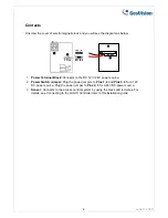
Contacts
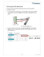
Unscrew the cover of electromagnetic lock and you will see the diagram as below:
1.
Power Terminal Block:
Connects to the DC 12V / 24V power source.
2.
Power Switch Jumper:
Plug the power jumpers to
Pins 1, 2
and
Pins 3, 4
for a 12V
DC power source. Plug the power jumper to
Pins 2, 3
for a 24V DC power source.
3.
Sensor:
Connects to the access control system by using the black and red wires. For
details, see
Connecting to the GV-AS Controller
later in this installation guide.
June 3, 2015
4