background image

+/-

Fuse Box

For details, see 

3.3.2 Connecting to a Vehicle

Chapter 3

 in 

GV-Compact DVR V3 

User’s Manual 

on the software DVD.

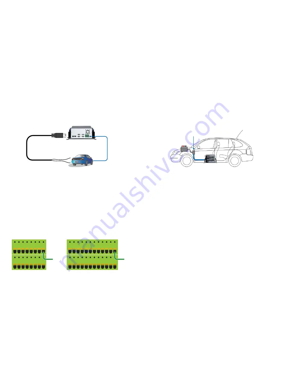
Connect to Pin 16 (4-Ch) or          

Pin 24 (8-Ch) of the 

Terminal Block on the 
GV-Compact DVR V3

Connect the white wire to the 

Vehicle’s Power Cable 

(

10

 ~ 

28 

VDC, 5A)

Connect the black wire to the 

Vehicle’s Ground Cable

The Supplied 

Power Cable

ACC wire from 

the Vehicle

GV-Compact DVR V3

Vehicle

1. Connect the 

white power

 wire of the unit to the 

positive-voltage

 power cable 

from the fuse box. 

2.  Remove the car door scuff plate and wire the power cable along the driver’s door 

toward the back seat.

3.  Use one of the two methods below to connect the black ground wire of the unit.

4.  Turn on the car ignition and the unit should start automatically within 5 seconds. 

Turn off the car ignition and the unit should shut down 30 seconds after the car 
ignition is off.


Method 1:

 Connect the 

black ground

 wire to the 

negative-voltage

 power 

cable from the fuse box.


Method 2: 

Connect the black ground wire to the vehicle’s chassis so that the 

wire contacts the bare metal.
When the black ground wire is connected correctly, the unit will automatically 
shut down 30 seconds after the car’s power is off. If the unit does not shut 
down, try to connect the black ground wire using the other method.

Connecting the ACC Wire

Connecting the Power Wire

1.  Locate and open the fuse box, which is usually located below the dashboard and 

to the left of the steering wheel.  

2.  Look for “cigarette lighter” fuse location, which is indicated in the fuse 

specification diagram on the fuse box or in the owner’s manual.

3.  Connect the ACC wire from the cigarette lighter fuse to 

Pin 16

 (4-Ch) or 

Pin 24


(8-Ch) on the terminal block.

Connecting Anti-Vibration ACC Models to a Vehicle

You need to connect the ACC model to ACC wire and power wire on the vehicle.

The following instructions are based on installation on a 

Toyota Zace Surf

. Since 

each vehicle differs in design, refer to the owner’s manual of your vehicle for details 
or have the installation done by a properly trained technician.

Using the fuse specification diagram, locate the power cables from the fuse box. You 
may need to use a voltmeter to determine positive-voltage and negative-voltage 
cables.

16

2 4 6 8 10 12 14

15

1 3 5 7 9 11 13

ACC wire of

the Vehicle

Terminal Block of 4-Ch

Terminal Block of 8-Ch

16

2 4 6 8 10 12 14

15 17

1 3 5 7 9 11 13

24

18 20 22

23

19 21

ACC wire of

the Vehicle

Summary of Contents for GV-LX4C3V

Page 1: ...ts and 1 hard drive bay Equipped with 2 USB ports and 2 hard drive bays Equipped with 2 USB ports 1 hard drive bay and 1 DVD RW drive Equipped with vibration absorbers 2 USB ports and 1 hard drive bay Model No GV LX4C3D1 GV LX4C3D2 GV LX4C3D2W GV LX4C3V Model Standard Standard Standard Anti Vibration ACC The 8 Channel Unit Description Equipped with 4 USB ports and 1 hard drive bay Equipped with 4 ...

Page 2: ... D Type Video Cable x 1 D Type Audio TV Spot Monitor Cable x 1 1 to 4 Camera Power Cable x 1 The 8 Channel Unit Power Cable x 1 Anti Vibration Model Shorting Cable x 1 Anti Vibration Model Camera Power Cable x 2 Lock Key x 2 1 Bay x 4 2 Bays Round Screws x 6 1 Bay x 12 2 Bays T Cap Screw x 4 1 Bay x 8 2 Bays Remote Control x 1 GV Compact DVR Quick Start Guide x 1 GV Compact DVR Software DVD x 1 GV...

Page 3: ... Vibration ACC models only The HDD converter allows you to install a 2 5 SATA HDD into GV Compact DVR V3 Working with this module GV Compact DVR V3 can expand the voltage load up to 10A 250V AC 10A 125V AC 5A 100V DC The WiFi USB Adaptor is designed to connect the GV IP devices to the wireless network It complies with IEEE 802 11 b g n Draft 3 0 standards for wireless networking The power adaptor ...

Page 4: ...ive for recording Writes the DVD disc for data backup Connects to power supply 75 Ω Video In Out Audio TV In Out VGA Monitor Port LAN Port I O Terminal Block External IR GPS Port 14 15 16 17 18 19 20 21 When using the Loop function turn the switches to OFF positions The switch number is corresponding to the channel number The default setting is ON Inputs 4 Blue Connectors CH1 4 Connects to cameras...

Page 5: ...HDD is reading or writing data Disk Full Fault LED Turns on when the HDD is full or read write error occurs Standard Model GV LX8CD1 GV LX8CD2 GV LX8CD2W The 8 Channel Unit 10 11 13 14 15 16 17 19 7 6 5 4 3 2 1 9 8 11 12 18 10 11 13 14 15 16 17 19 7 6 5 4 3 2 1 9 8 18 20 Anti Vibration ACC Model GV LX8CV1 10 11 13 14 15 16 17 19 7 6 5 4 3 2 1 9 8 18 20 GV LX8CV2 10 11 13 14 15 16 19 7 6 5 4 3 2 1 ...

Page 6: ... backup Connects to power supply Connects to the network Inputs 5 Blue Connectors CH1 5 Connects to cameras Outputs 5 Black Connectors CH1 5 Loops out each camera input to monitors Inputs 3 Blue Connectors CH6 8 Connects to cameras Outputs 3 Black Connectors CH6 8 Loops out each camera input to monitors TV Output 1 Black Connector QUAD Connects to a TV monitor Spot Monitor Output 1 Black Connector...

Page 7: ...power by using the supplied power adaptor 2 Connect to cameras 4 Ch Using the supplied D Type Audio TV Spot Monitor Cable connect microphones to the four white connectors and a speaker to the red connector 8 Ch Using the supplied D Type Audio Cable connect microphones to the eight red connectors and a speaker to the white connector B Using the VGA cable supplied by the monitor manufacturer connect...

Page 8: ...daptor DC 12V 5A which can be purchased from GeoVision 1 Connect the Shorting Cable to Pins 14 and 16 4 Ch or Pins 22 and 24 8 Ch on the terminal block 2 Power on the unit by using a power adaptor The unit automatically starts after powering up for 5 seconds 3 Set up the settings of the unit such as storage images recording and etc through its OSD or Web interface 4 Remove the power adaptor The un...

Page 9: ...rectly the unit will automatically shut down 30 seconds after the car s power is off If the unit does not shut down try to connect the black ground wire using the other method Connecting the ACC Wire Connecting the Power Wire 1 Locate and open the fuse box which is usually located below the dashboard and to the left of the steering wheel 2 Look for cigarette lighter fuse location which is indicate...

Page 10: ...st be assigned an IP address to make it accessible There are two ways to assign an IP address Using OSD Menu and Using Web Interface For detail on assigning an IP address using the Web interface of the GV Compact DVR V3 see Connecting with a PC Chapter 5 in GV Compact DVR V3 User s Manual on the software DVD To use the OSD menu to assign a static IP 1 Press the Menu button select NETWORK and then ...

Page 11: ...ime when viewing live video 2 A B C Indicates the type of device defined for the GV Compact DVR V3 3 Monitoring icon Appears when the monitoring is activated 4 Manual recording icon or Schedule recording icon Appears when the recording is started manually or by schedule 5 Input icon Appears when the input device is installed and activated 6 Channel number Camera name Displays the camera number or ...

Page 12: ... important notes below and then follow the instructions 1 In the Live View window click the Show System Menu button and select Remote Config This dialog box appears 2 Click the Browse button to locate the firmware file img saved at your local computer 3 Click the Upgrade button to start the upgrade 7 Basic Operations 8 Upgrading System Firmware Operations Date Time Adjustment Recording Operation S...

Reviews: