


Quick Start Guide
1
Introduction
Welcome to the
GV-Compact DVR V3 Quick Start Guide
. In the following sections,
you will learn about the basic installations and configurations of the GV-Compact
DVR V3. For a detailed user’s manual, see
GV-Compact DVR V3 User’s Manual
on
the GV-Compact DVR V3 software DVD.
© 2011 GeoVision, Inc. All rights reserved.
All GeoVision Products are manufactured in Taiwan.
2011/10
English
CDVRV3-QG-B
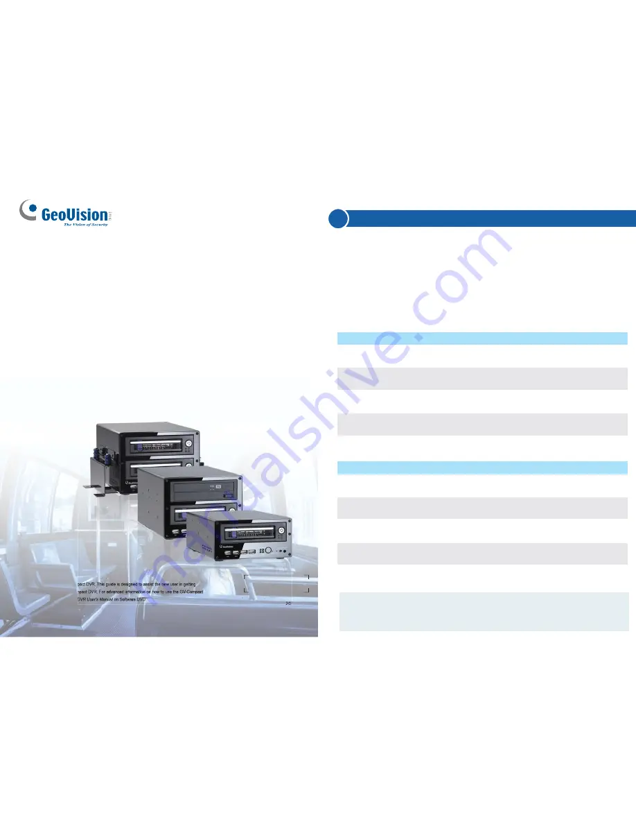
The 4-Channel Unit
GV-Compact DVR V3
Thank you for purchasing GV-Compact DVR. This guide is designed to assist the new user in getting
immediate results from the GV-Compact DVR. For advanced information on how to use the GV-Compact
DVR, please refer to
GV-Compact DVR User's Manual
on Software DVD.
Models
Description
Equipped with 2 USB ports and 1 hard drive
bay.
Equipped with 2 USB ports and 2 hard drive
bays.
Equipped with 2 USB ports, 1 hard drive
bay and 1 DVD-RW drive.
Equipped with vibration absorbers, 2 USB
ports and 1 hard drive bay.
Model No.
GV-LX4C3D1
GV- LX4C3D2
GV- LX4C3D2W
GV-LX4C3V
Model
Standard
Standard
Standard
Anti-Vibration
ACC
The 8-Channel Unit
Description
Equipped with 4 USB ports and 1 hard drive
bay.
Equipped with 4 USB ports and 2 hard drive
bays.
Equipped with 4 USB ports, 1 hard drive
bay and 1 DVD-RW drive.
Equipped with vibration absorbers, 4 USB
ports and 1 hard drive bay.
Equipped with vibration absorbers, 4 USB
ports and 2 hard drive bays.
Model No.
GV-LX8CD1
GV-LX8CD2
GV-LX8CD2W
GV-LX8CV1
GV-LX8CV2
Model
Standard
Standard
Standard
Anti-Vibration
ACC
Anti-Vibration
ACC
Note:
For the Anti-vibration ACC models (GV-LX4C3V, GV-LX8CV1 and
GV-LX8CV2), it is
necessary
to use the hard drive for notebook, vehicle
or
surveillance applications to prevent vibration and shock hazard.