
GeoSIG Ltd
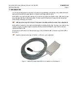
GS_GXR_GPS_User_Manual_V03.doc / 22.06.2010
Page 2
GPS User Manual
2. Electrical Connection
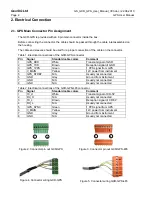
2.1. GPS Main Connector Pin Assignment
The GXR-GPS is provided with an 8 pin main connector inside the box.
Before connecting the connector, the cable should be passed through the cable inlet assembled on
the housing.
The cable end sleeves should be used for a proper connection of the cable on the connector.
Table 1. Electrical connections of the GXR-GPS connector
Pin
Signal
Standard cable colors
Comment
1
GPS_RXD
White
Transmit signal of GSR
2
GPS_TXD
Brown
Reception signal of GSR
3
GPS_1PPS
Green
1 PPS signal from GPS
4
V_MAIN
Yellow
12V power from instrument
5
GPS_STDBY
N/A
Usually not connected
6
GND
Grey
Ground from instrument
7
GND
N/A
Usually not connected
8
GND
N/A
Usually not connected
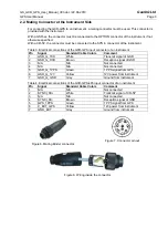
Table 2. Electrical connections of the GXR-GPS-485 connector
Pin
Signal
Standard cable colors
Comment
1
TX_H
White
Transmit signal of CR-5P
2
RX_H
N/A
Usually not connected
3
TX_L
Brown
Reception signal of CR-5P
4
RX_L
N/A
Usually not connected
5
GPS_SYNC
Green
1 PPS signal from GPS
6
V_MAIN
Yellow
12V power from instrument
7
GND
Grey
Ground from instrument
8
GND
N/A
Usually not connected
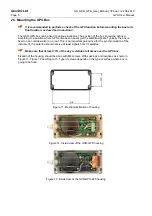
Figure 2. Connector pin out GXR-GPS
1
8
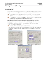
8
1
Figure 3. Connector pin out GXR-GPS-485
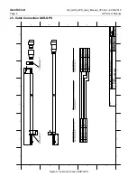
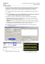
Figure 4. Connector wiring GXR-GPS
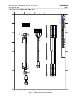
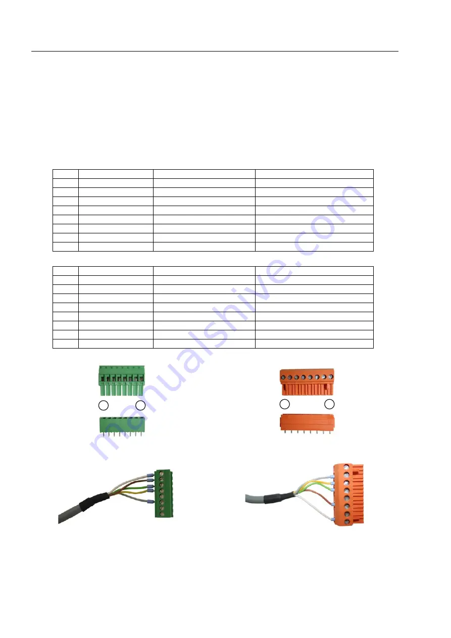
Figure 5. Connector wiring GXR-GPS-485