

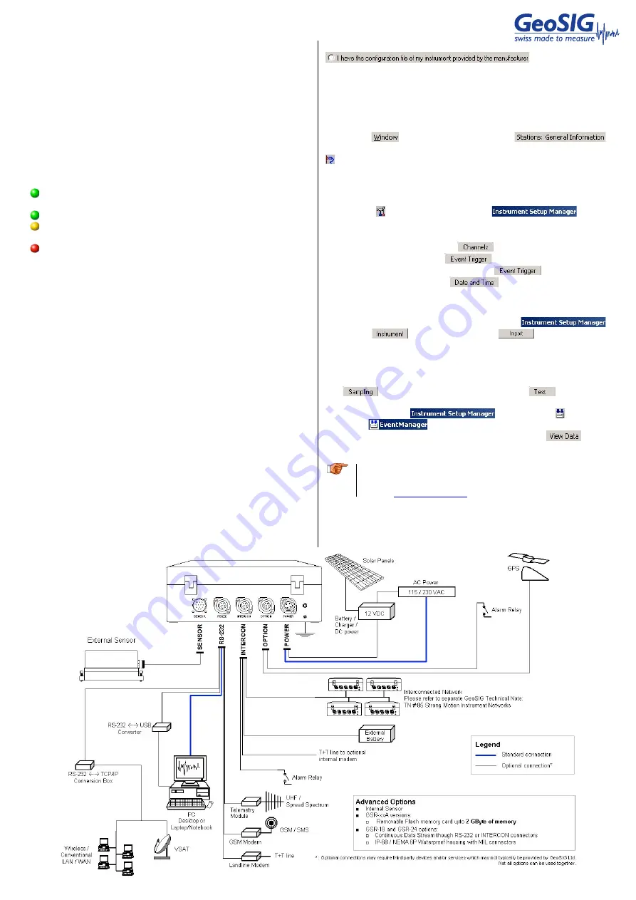
#) PC refers to desktop or laptop / notebook models of personal computers
GS_GSR_GCR_QuickUserManual_V03.doc / 09.12.2014
If the site is in an area where snowfall can occur, it is preferred to
mount the GPS module on a wall rather than on the roof.
Step 8. GSR Startup
Turn on the GSR via the Main Switch located next to the flat
cable inside the housing. Observe the version of the firmware on
the LCD, followed by the message “GSR startup”. The progress is
then shown with dots. Allow up to 1 minute for the startup, until
when the LCD switches to standard display mode. If not, please
check connections and refer to the GSR manual under the
Manuals folder on the supplied USB-Stick for troubleshooting.
The LEDs meanings are as follows:
AC
(
A
ctive
C
harge) illuminates when external power
input is present at the POWER connector.
RUN
flashes when GSR is running.
EVENT
illuminates during recording and flashes when there
are events recorded in the memory.
ERROR
flashes to indicate a warning condition and flashes
faster to indicate an error condition.
Step 9. Software Installation
To install GeoDAS, a PC
#)
running Microsoft Windows™
operating system (Windows XP™ is preferred) is needed. Insert
the supplied USB-Stick in the PC
#)
. GeoSIG menu should appear
shortly, from which you can select to install GeoDAS. If not, then
launch setup.exe under the GeoDAS folder on the supplied USB-
Stick.
Select the Normal mode installation at the prompt and enter the
GeoDAS-DAP code when required; if DAP option has been
purchased. If you do not have a DAP code, simply enter 0. In that
case, the basic functions will be operational. You can later
purchase and enter a valid DAP code to unlock the extra
functions.
Step 10. First Connection
Once GSR is correctly operating and the GeoDAS is installed,
connect the communication cable to the PC
#)
on a serial port
(COM port) and to the GSR on the RS-232 connector.
Launch GeoDAS on the PC
#)
. If it’s the first time you launch
GeoDAS, you should have a window asking if you would like to
configure one or more stations, just answer yes.
Then you have several options for the configuration of the station,
the recommended one is the second choice:
Select the COM port where the GSR is connected. The Station
Configuration file
*
.gsc can be found under the Config folder. The
file name is typically the serial number that can be found on the
label of the GSR. For adding several stations, you can use the
global
*
.gsc file typically named after the GeoSIG job number.
Under the
menu, after activating the
window, you can select the above-configured GSR and click the
button on the GeoDAS toolbar to connect.
Step 11. GSR Configuration
Now connected to the GSR, you can further configure it by
clicking the button, which opens the
.
Usually the most important settings that should be checked are:
•
Sensor full scale under the
tab
•
Trigger levels under the
tab
•
Pre and Post event times under the
tab
•
GPS operation under the
tab
Please note that you can always restore the factory configuration
of the GSR using the Instrument Configuration file
*
.ist that is
under the Config folder and import it via the
under the
tab by clicking the
button. The file
name is either the serial or the job number.
Step 12. Testing the Station
As a minimum, the zero level of the sensor must be checked in
the
tab for reasonable values. In the
tab, all the
tests must be executed and a Test Pulse must be recorded. After
the tests, close the
and click the button to
open the
window. After a while the recorded test
file will be listed. Right click on the file and select
. This
will download the file and plot it.
a
Further information can be found in the product manuals
under the Manuals folder on digital media or on our
website
www.geosig.com
.


