


MODEL 6180 VERTICAL IN-PLACE INCLINOMETER SYSTEM
| INSTALLATION |
5
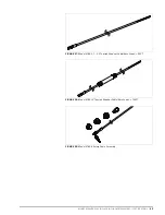
3.
Retract the spring sleeve on the second sensor and mate the ball stud of the
first sensor to the receiver of the second sensor by connecting them
together using a lateral motion.
9:
FIGURE 9:
Retract the Spring Sleeve
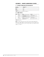
4.
Capture the ball stud by releasing the spring sleeve (make sure the sleeve
returns to its initial position).
10:
FIGURE 10:
Capture the Ball Stud
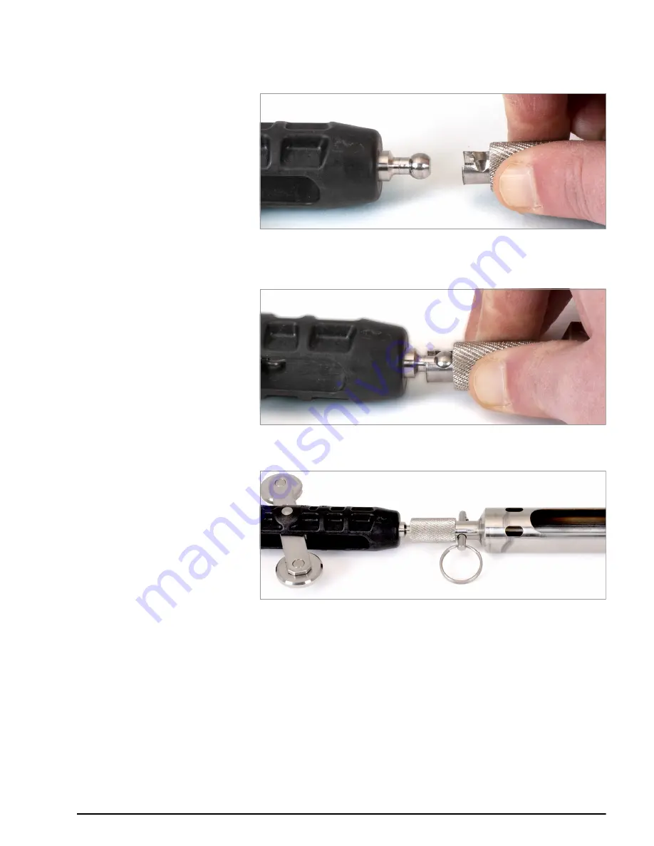
5.
Reinsert the locking pin to prevent the sleeve from retracting while in use.
11:
FIGURE 11:
Completed Connection
6.
Plug the male connector of the first sensor’s signal cable into the female
connector of the second sensor’s signal cable.
Caution!
When connecting the sensors, make sure to align the two
orientation dots on the outside of the female connector with the orientation
dot on the outside of the male connector. This will ensure the pins and
receptacles on the interior of the connectors align correctly. Push the male
and female connectors together until they are completely mated.


