


7
ENGLISH
MILORD AUTOMATED SYSTEM
The MILORD automated system for residential sliding gates is an electro-
mechanical operator which transmits motion to the leaf through a pinion
gear suitably coupled to a rack fitted on the gate.
The non-reversing system ensures mechanical locking when the motor
is not operating and, therefore, installing a lock is unnecessary. A handy
release facility makes it possible to move the gate in the event of a power
cut or fault.
This operator has no mechanical clutch, and, therefore, requires a control
unit with electronic clutch.
In the “C” versions, MILORD operators have the electronic control unit built
into the operator body.
. DESCRIPTION AND TECHNICAL SPECIFICATIONS
t
eChniCal
speCifiCations
of
operators
Model
MILORD
5-5C
MILORD
424-424C
MILORD
8-8C
Power supply
230V~ 50Hz
24 Vdc
230V~ 50Hz
Absorbed power
350 W
70 W
500 W
Absorption
1.5 A
3 A
2.2 A
Electric motor rpm
1400
Thrust capacitor
10 µF 400V
/
12.5 µF
400V
Reduction ratio
1:25
Pinion
Z16
Rack
module 4
Max torque
18 Nm
13.5 Nm
24 Nm
Max thrust
45 daN
40 daN
65 daN
Thermal protection on winding
140°C
/
140°C
Use frequency
30%
100%
40%
Operating ambient temperature
-20°C +55°C
Operator weight
10 Kg
11Kg
Protection class
IP44
Max gate weight
500 Kg
400 Kg
800 Kg
Gate speed
12 m/min
Max gate length
15 m
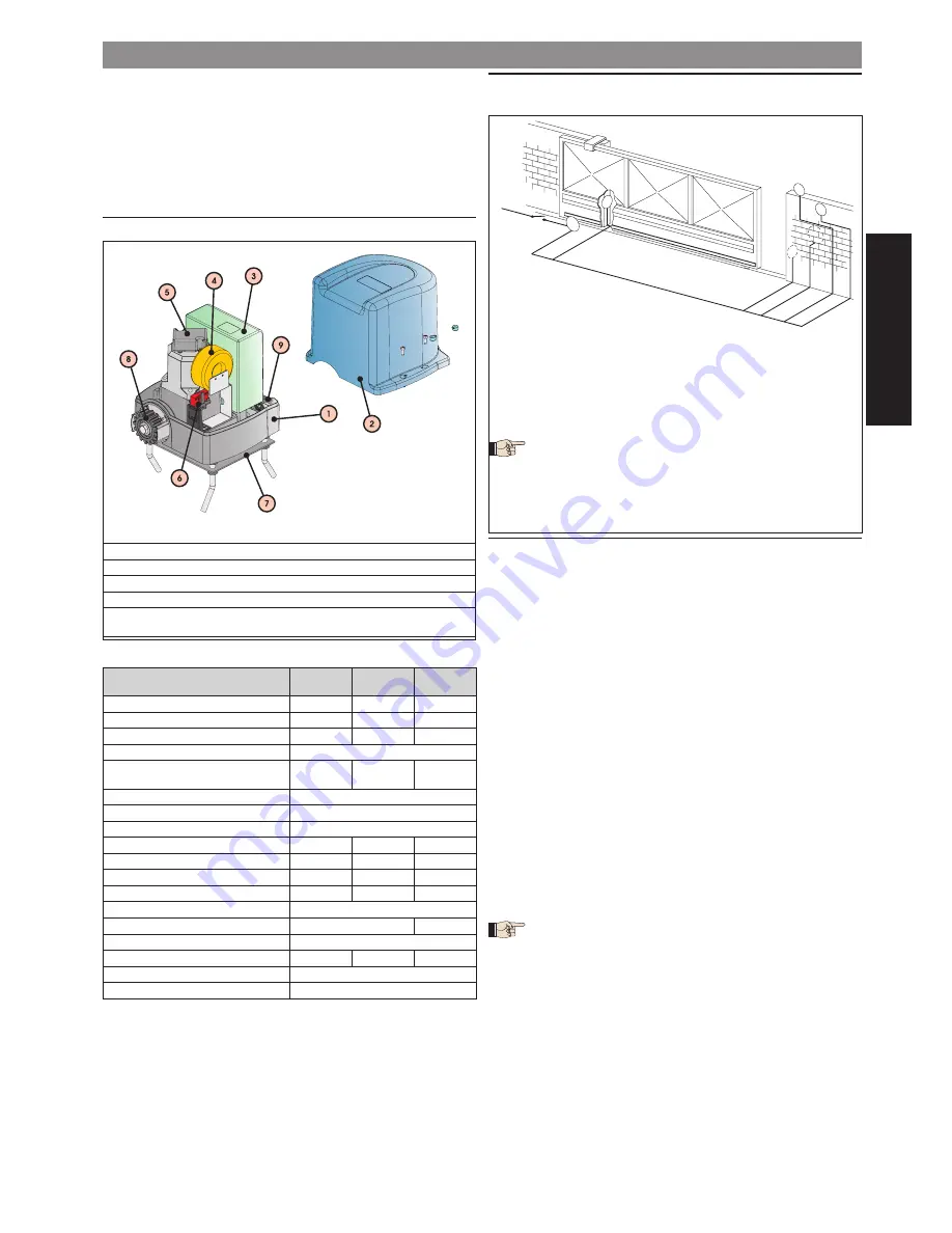
1 Gearmotor
6 Magnetic sensor
2 Protective housing
7 Foundation plate
3 Control unit *
8 Pinion
4 Toroidal transformer **
9 Release device
5 Encoder **
* Standard supply only in “”C”” versions
** For MILORD 424C model only
1 Gearmotor
6 Magnetic sensor
2 Protective housing
7 Foundation plate
3 Control unit *
8 Pinion
4 Toroidal transformer **
9 Release device
5 Encoder **
* Standard supply only in “”C”” versions
** For MILORD 424C model only
Fig. 1
Fig. 1
2. ELECTRICAL SET-UP
(standard system)
3X1,5m
m
2
2
2
5
4
1
230V~
3x0,5 mm
2
2x0,5 mm
2
2x0,5 mm
2
2x1,5 mm
2
3x0,5 mm
2
3
3. INSTALLING THE AUTOMATED SYSTEM
3.. PRELIMINARY CHECKS
To ensure a correctly operating automated system, the structure of the
existing gate or gate to be built must satisfy the following requirements:
the weight of the gate must comply with the data in the technical spe-
cifications table;
sturdy, rigid gate structure;
smooth leaf surface (without any projections);
smooth, uniform gate movement, without any friction during the entire
travel;
no sideward leaf swings;
top and bottom sliding systems must be in excellent condition. It is prefe-
rable to use a ground-level guide with rounded groove to obtain reduced
sliding friction.
only two sliding wheels;
mechanical safety stops required to prevent the danger of gate derail-
ment; these stops must be firmly secured to the ground or to the ground-
level guide at about 40 mm beyond the travel limit position.
no mechanical closing locks.
We advise you to carry out the metalwork jobs before installing the auto-
mated system.
The condition of the structure directly influences the reliability and safety
of the automated system.
3.2. INSTALLING THE OPERATOR
Assemble the foundation plate as in Fig.3.
Dig a cavity for the foundation plate as shown in Fig. 4. The foundation
plate must be located as shown in Fig. 5 (right closing) or Fig.6 (left closing)
to ensure correct meshing between rack and pinion.
We advise you to place the plate on a cement base about 50 cm
off the ground (fig.7).
Lay the flexible pipes for routing the connection cables between gear-
motor, accessories and electrical power supply. The flexible pipes must
protrude by about 3 cm from the hole on the plate.
•
•
•
•
•
•
•
•
•
1.
2.
3.
Operator with built-in control unit (supply a suitable foundation plate)
Photocells
Key push-button
Flashing lamp
Receiver
1) To lay cables, use adequate rigid and/or flexible tubes.
2) Always separate connection cables of low voltage accessories
from those operating at 230 V~. To prevent any interference wha-
tever, use separate sheaths.
1.
2.
3.
4.
5.
Fig. 2
Fig. 2


