background image

20

Genie S-120 & Genie S-125

Part No. 62756

Operator's Manual

First Edition · Fourth Printing

FUNCTION TESTS

Test Limited Drive Speed

62 Press down the foot switch.

63 Raise the boom to 10° above horizontal.

64 Slowly move the drive control handle to the full

drive position.

Result: The maximum achievable drive speed

with the boom raised should not exceed 1 foot
per second (0.3 meters per second).

Note: The machine will travel 40 feet in 40 seconds
(12.2 meters in 40 seconds).

65 Lower the boom to the stowed position.

66 Extend the boom 4 feet (1.2 m).

67 Slowly move the drive control handle to the full

drive position.

Result: The maximum achievable drive speed

with the boom extended should not exceed 1
foot per second (0.3 meters per second).

Note: The machine will travel 40 feet in 40 seconds
(12.2 meters in 40 seconds).

If the drive speed with the boom raised or
extended exceeds 1 foot per second (0.3 meters
per second), immediately tag and remove the
machine from service.

68 Raise the boom to horizontal. Extend the boom

as far as it will go.

69 Slowly move the drive control handle to the full

drive position.

Result: The maximum achievable drive speed

with the boom fully extended should not exceed
0.6 feet per second (0.2 meters per second).

Note: The machine will travel 40 feet in 70 seconds
(12.2 meters in 70 seconds).

Test Auxiliary Controls

70 Shut off the engine.

71 Pull out the red Emergency Stop button to

the 

ON

 position.

72 Press down the foot switch.

73 Simultaneously press and hold the auxiliary

power button and activate each function control
handle, toggle switch or button.

Note: To conserve battery power, test each
function through a partial cycle.

Result: All boom and steer functions should

operate.
Machines equipped with the auxiliary power
drive option: The drive function should operate.

Summary of Contents for S-120

Page 1: ...Operator s Manual with Maintenance Information First Edition Fourth Printing Part No 62756 ...

Page 2: ...er Printed in U S A Important Read understand and obey these safety rules and operating instructions before operating this machine Only trained and authorized personnel shall be permitted to operate this machine This manual should be considered a permanent part of your machine and should remain with the machine at all times If you have any questions call Genie Industries Contents Page Safety Rules...

Page 3: ...anual 1 Avoid hazardous situations Know and understand the above principle before going on to the next section 2 Always perform a pre operation inspection 3 Always perform function tests prior to use 4 Inspect the work place 5 Only use the machine as it was intended You read understand and obey Manufacturer s instructions and safety rules safety and operator s manuals and machine decals employer s...

Page 4: ... 13 72 Allow for platform movement electrical line sway or sag and beware of strong or gusty winds Keep away from the machine if it contacts energized power lines Personnel on the ground or in the platform must not touch or operate the machine until energized power lines are shut off Do not use the machine as a ground for welding unless the machine is equipped with the weld line to platform option...

Page 5: ...of the platform or the load Increasing the area exposed to the wind will decrease machine stability Use extreme care and slow speeds while driving the machine in stowed position across uneven terrain debris unstable or slippery surfaces and near holes and drop offs Do not drive the machine on or near uneven terrain unstable surfaces or other hazardous conditions with the boom raised or extended Ma...

Page 6: ...e anchorage point provided in the platform It is recommended that operators wear an approved hard hat when operating the machine SAFETY RULES Do not sit stand or climb on the platform guard rails Maintain a firm footing on the platform floor at all times Do not climb down from the platform when raised Keep the platform floor clear of debris Lower the platform entry mid rail or close the entry gate...

Page 7: ...ntilated area away from sparks flames and lighted tobacco Do not operate the machine in hazardous locations or locations where potentially flammable or explosive gases or particles may be present Observe and use the circle and square markings and the color coded direction arrows on the platform controls and drive chassis for drive and steer functions Do not lower the boom unless the area below is ...

Page 8: ...moderate injury Yellow without safety alert symbol used to indicate the presence of a potentially hazardous situation which if not avoided may result in property damage Green used to indicate operation or maintenance information Damaged Machine Hazards Do not use a damaged or malfunctioning machine Conduct a thorough pre operation inspection of the machine and test all functions before each work s...

Page 9: ...lect button 7 LCD readout screen 8 Emergency Stop button 9 Gasoline LPG models Choke button Deutz Diesel models Glow plug button 10 Key switch for off platform ground selection 11 Engine start button 12 Auxiliary power button 13 High speed function enable button 14 Low speed function enable button 15 Alarm 16 Platform level up down buttons 17 S 125 models Jib boom up down buttons 18 Platform rotat...

Page 10: ...ndicator light 16 Check engine indicator light Platform Control Panel 1 Platform rotate switch 2 Platform level switch 3 Platform Not Level indicator light 4 Machine Not Level indicator light 5 Retract Boom indicator light 6 Raise Boom indicator light 7 Horn button 8 Generator button with indicator light option 2 6 5 7 8 9 10 24 25 20 26 27 28 4 3 9 Auxiliary power button with indicator light 10 D...

Page 11: ... lights 11 12 13 15 14 17 19 18 16 20 21 22 23 22 Drive select button with indicator lights Machine on incline symbol Low range operation for inclines Machine on level surface symbol High range operation for maximum drivespeed 23 Singleaxisproportional control handle for boom extend retractfunction 24 Extend axle button with indicator light 25 Retract axle button with indicator light 26 Drive enab...

Page 12: ... a machine before the operator performs the function tests The Pre operation Inspection also serves to determine if routine maintenance procedures are required Only routine maintenance items specified in this manual may be performed by the operator Refer to the list on the next page and check each of the items and locations for modifications damage or loose or missing parts A damaged or modified m...

Page 13: ...per fluid level Add distilled water if needed See Maintenancesection Check the following components or areas for damage and improperly installed loose or missing parts o Electrical components wiring and electrical cables o Hydraulic hoses fittings cylinders and manifolds o Fuel and hydraulic tanks o Drive and turntable motors and drive hubs o Boom and axle wear pads o Tires and wheels o Engineandr...

Page 14: ...Oil Level Maintaining the proper engine oil level is essential to good engine performance and service life Operating the machine with an improper oil level can damage engine components Check the oil level with the engine off 1 Check the engine oil dipstick Add oil as needed Cummins models Result The oil level should be within the L and H marks on the dipstick Deutz models Result The oil level shou...

Page 15: ...he vent caps Adding terminal protectors and a corrosion preventative sealant will help eliminate corrosion on the battery terminals and cables Perkins 1004 42 Engine 8 9 quarts Oil capacity including filter 8 4 liters Perkins 1004 42 Engine Oil viscosity requirements below 32 F 0 C 0W 13 F to 68 F 25 C to 20 C 5W 20 10 F to 104 F 12 C to 40 C 10W 30 14 F to 122 F 10 C to 50 C 15W 40 above 23 F 5 C...

Page 16: ...ng system problems 1 Check the fluid level in the coolant recovery tank Add fluid as needed Result The fluid level should be in the NORMAL range Bodily injury hazard Fluids in the radiatorareunderpressureand extremely hot Use caution when removing cap and adding fluids The Schedule There are five types of maintenance inspections that must be performed according to a schedule daily quarterly six mo...

Page 17: ...ection 4 Inspect the work place 5 Only use the machine as it was intended 1 Select a test area that is firm level and free of obstruction At the Ground Controls 2 Turn the key switch to ground control 3 Pull out the red Emergency Stop button to the ON position Result The LCD screen will come on and display no error messages The beacon if equipped should flash Note In cold climates the LCD readout ...

Page 18: ...p button and the boom down button Result The boom should raise and lower normally 13 At the ground controls push and hold a function enable speed select button and push the boom extend button and the boom retract button Result The boom should extend and retract normally Test the Machine Functions 14 Do not press and hold a function enable speed select button Attempt to activate each boom and platf...

Page 19: ...D screen Result The LCD screen should display 10 10 50 65 25 Push one of the LCD screen buttons shown until BOOM LENGTH is displayed 26 Extend the boom and observe the LCD screen Result The LCD screen should display at 0 0 80 100 100 27 Retract the boom At the Platform Controls Test Emergency Stop 28 Turn the key switch to platform control 29 Push in the platform red Emergency Stop button to the O...

Page 20: ...the Steering 43 Push the steer mode select button for square end bluearrow steer 44 Press down the foot switch 45 Slowly move the drive steer control handle in the direction indicated by the blue triangle on the control panel OR press the thumb rocker switch in thedirectionindicatedbythebluetriangle Result The square end wheels should turn in the direction that the blue triangles point on the driv...

Page 21: ...w arrow on the control panel until the machine begins to move then return the handle to the center position Result The machine should move in the direction that the yellow arrow points on the drive chassis then come to an abrupt stop Note The brakes must be able to hold the machine on any slope it is able to climb Blue Yellow Test the Drive Enable System 58 Press down the foot switch and lower the...

Page 22: ... in 40 seconds If the drive speed with the boom raised or extended exceeds 1 foot per second 0 3 meters per second immediately tag and remove the machine from service 68 Raise the boom to horizontal Extend the boom as far as it will go 69 Slowly move the drive control handle to the full drive position Result The maximum achievable drive speed with the boom fully extended should not exceed 0 6 feet...

Page 23: ...n and practice the principles of safe machine operation contained in this operator s manual 1 Avoid hazardous situations 2 Always perform a pre operation inspection 3 Always perform function tests prior to use 4 Inspect the work place Know and understand the above principles before going on to the next section 5 Only use the machine as it was intended Fundamentals The Work Place Inspection helps t...

Page 24: ... the Emergency Stop button is pushed in to the OFF position Selecting and operating the ground controls will override the platform Emergency Stop button Do Not Operate Unless You learn and practice the principles of safe machine operation contained in this operator s manual 1 Avoid hazardous situations 2 Always perform a pre operation inspection 3 Always perform function tests prior to use 4 Inspe...

Page 25: ...r switch located on top of the drive control handle Use the color coded direction arrows on the platform controls and the drive chassis to identify the direction the wheels will turn Auxiliary Controls Use auxiliary power if the primary power source engine fails 1 Turn the key switch to ground or platform control 2 Pull out the red Emergency Stop button to the ON position 3 Press down the foot swi...

Page 26: ... are moved Always use the color coded direction arrows on the platform controls and the drive chassis to identify the direction the machine will travel OPERATINGINSTRUCTIONS Non regulated Generator if equipped To operate the generator press the generator button The indicator light will come on and the engine rpm will automatically be in turtle symbol mode The engine will continue to run the drive ...

Page 27: ...the boom until the indicator light is off Machine Not Level indicator light flashing The tilt alarm will be sounding when this light is flashing Move the machine to a firm level surface Platform Not Level indicator light flashing The tilt alarm will be sounding when this light is flashing The Platform Level toggle switch will only work in the direction that will level the platform Level the platfo...

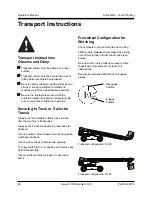
Page 28: ...e sure vehicle capacity loading surfaces and straps or lines are sufficient to withstand machine weight see Specifications section Be sure the turntable is secured with the turntable rotation lock before transporting Be sure to unlock the turntable for operation Securing to Truck or Trailer for Transit Always use the turntable rotation lock pin each time the machine is transported Always chock mac...

Page 29: ...Anchorage Point 2 43594 Notice Maximum Capacity 750 lbs S 120 1 44986 Notice Max Manual Force 90 lbs CE 1 61227 Ground Control Panel 1 Decal Inspection Use the pictures on the next page to verify that all decals are legible and in place Below is a numerical list with quantities and descriptions Part No Description Quantity 65182 Platform Control Panel 1 65264 Cosmetic Genie S 125 1 65265 Cosmetic ...

Page 30: ...28 Genie S 120 Genie S 125 PartNo 62756 Operator s Manual First Edition Fourth Printing DECALS ...

Page 31: ...axles extended Power source Perkins Diesel 1004 42 choice Deutz Diesel F4L913 Cummins Diesel 4B3 9 Drive speed stowed 3 0 mph 4 4 km h 40 ft 9 1 sec 12 2 m 9 1 sec Drive speed 0 7 mph 1 1 km h raised or extended 40 ft 40 sec 12 2 m 40 sec Drive speed 0 4 mph 0 6 km h fully extended 40 ft 70 sec 12 2 m 70 sec S 120 Controls 12V DC proportional Platform dimensions 96 x 36 in length x width 2 4 m x 9...

Page 32: ...axles extended Power source Perkins Diesel 1004 42 choice Deutz Diesel F4L913 Cummins Diesel 4B3 9 Drive speed stowed 3 0 mph 4 4 km h 40 ft 9 1 sec 12 2 m 9 1 sec Drive speed 0 7 mph 1 1 km h raised or extended 40 ft 40 sec 12 2 m 40 sec Drive speed 0 4 mph 0 6 km h fully extended 40 ft 70 sec 12 2 m 70 sec S 125 Controls 12V DC proportional Platform dimensions 96 x 36 in length x width 2 4 m x 9...

Page 33: ...73 27 11 455 0355 55 11 4055 2499 55 11 4043 1661 Genie Holland Genie Scandinavia Genie France Genie Iberica Genie Germany Genie U K Genie Mexico City Phone Fax Phone Fax Phone Fax Phone Fax Phone Fax Phone Fax Phone Fax 31 70 51 78836 31 70 51 13993 46 31 3409612 33 0 2 37 26 09 99 33 0 2 37 26 09 98 34 93 579 5042 34 93 579 5059 49 0 4202 88520 49 0 4202 8852 20 44 0 1476 584333 44 0 1476 584334...

Reviews: