Genie PCB218 User Manual Download Page 3

This worksheet is copyright © New Wave Concepts Limited. All rights reserved.

It may be photocopied for classroom or non-commercial use.    w

ww

ww

w..ggeenniieeoonnlliinnee..ccoom

m

Page 3 of 8  

®

221188 GENIE 18 Project Kit.pdf  

®

Version 1.5

G

GEEN

NIIEE 1188 PPrro

ojjeecctt K

Kiitt ((PPC

CBB221188))

Telling the GENIE your wishes  

33

A

Avvaaiillaabbllee SSiiggnnaallss

These are the iinn

ppuutt aanndd oouuttppuutt

ssiiggnnaallss available 

in your flowcha

rt:

IInnppuutt

D

Deessccrriippttiioonn

A/D0 to A/D2

Analogue or dig

ital

D6 and D7

Digital

O

Ouuttppuutt

D

Deessccrriippttiioonn

Q0 to Q7

Medium-power

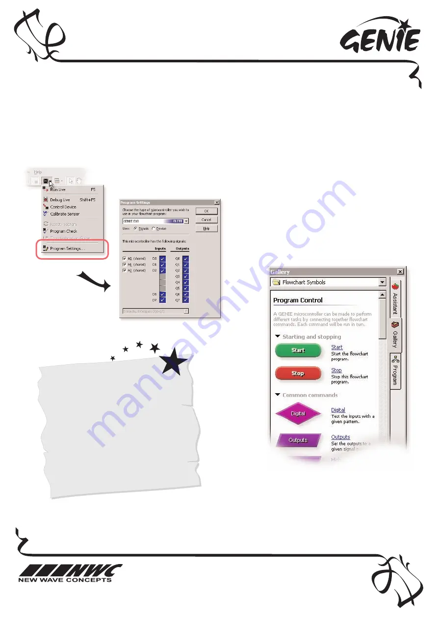
First of all, you need to tell GENIE which type of chip you are using. To do this,
click on the M

Miiccrrooccoonnttrroolllleerr button on the toolbar and choose PPrrooggrraam

m SSeettttiinnggss.

For your project to work, you need to tell the GENIE microcontroller what it should do.
This involves writing a sequence of commands in a fflloow

wcchhaarrtt. Your flowchart is then sent down the

cable and stored on the GENIE chip. By changing the flowchart, you can vary how the GENIE behaves.

Select an 18-pin G

GEEN

NIIEE chip.

The inputs and output signals for this type
of microcontroller are fixed, so click on O

OK

K

when you are ready to continue.

ÁÁ

Ã

Ã

You can now decide which commands you
want your GENIE to perform. To do this,
drag commands from the G

Gaalllleerryy.

See the next worksheet for flowchart ideas.

Summary of Contents for PCB218

Page 1: ...t contains 8 separate transistors that allow each output to control more powerful things Medium power outputs controlled by signals Q Q0 0 to Q Q7 7 Low power outputs signals these are output signals...

Page 2: ...n and the dot next to pin 1 is at the same corner as the 1 shown on the board The green LED should be fitted so that the flat edge of the LED lines up with the flat edge shown on the board The diode s...

Page 3: ...n Q0 to Q7 Medium power First of all you need to tell GENIE which type of chip you are using To do this click on the M Mi ic cr ro oc co on nt tr ro ol ll le er r button on the toolbar and choose P Pr...

Page 4: ...mple Use the H HI IG GH H command to turn a single output on Use the L LO OW W command to turn a single output off Use the O OU UT TP PU UT TS S command to control several outputs The flowchart on the...

Page 5: ...d to a digital signals The ANALOGUE command allows you to check if a signal lies within a given range With GENIE analogue levels can vary between 0 0 the lowest level and 2 25 55 5 the highest Double...

Page 6: ...g gr re ee en n s st ta at tu us s L LE ED D o on n t th he e p pr ro oj je ec ct t k ki it t w wi il ll l f fl la as sh h a as s t th he e d do ow wn nl lo oa ad d t ta ak ke es s p pl la ac ce e I I...

Page 7: ...o on n p pr ro ob bl le em ms s C Ca ab bl le e Circuit Wizard GENIE Design Studio and the GENIE Programming Editor software all check and report problems involving the cable If given follow through o...

Page 8: ...0V Download Socket 100k 4 5 6V STATUS 10k 330 D7 1N4148 220 F 100nF D6 Q1 Q2 Q3 Q4 Q5 1 2 3 4 5 6 7 8 9 10 11 12 13 14 15 16 17 18 ULN2803 Q6 Q7 Q0 A D2 A D1 A D0 D2 A ST PR R 0V Q0 Q1 Q2 Q3 Q4 Q5 Q6...

Reviews: