CONTROLS AND INSTRUMENTS
WARNING
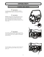
Always ensure that the machine level indicator (D) is at zero (0)
degrees before raising the boom. Raising the boom with an
unlevel machine may cause the machine to overturn, resulting
in injury or death.
WARNING
Use the frame sway control to level the machine only when the
boom angle indicator is at 0 degrees or less. Using the frame
sway control when the angle indicator is more than 0 degrees
may cause the machine to overturn, resulting in injury or death.
SWAY
CONTROL
PUMP OFF
BRAKE ON
(C) LETTER VISIBLE = 3,000 LBS
(D) LETTER VISIBLE = 2,000 LBS
P/N 3-1483
0
(1.22)
M ETER
F EET
(6.10)
2 8
(8.54)
24
(7.32)
20
4
455 N ORTH S UPERIOR AV ENU E
M ACHINE O N A F IRM, LEVEL
S URFACE WITH U NDA MAGED,
P ROPERLY INF LA TED CA LCIUM
CA PACITY IS P ER ANS I B56.6
LOA D LIMITS / HO RIZON TAL BOO M
(B) LETTER V ISIBLE = 4,000 LBS
OR OPTIONA L FOA M F ILLED TIRES.
CH LORID E SOLUTION FILLED TIRES
RATED LIFT CA PACITIES ARE WITH :
LAST FULLY VIS IBLE LETTER
(A) LETTER VISIBLE = 6,000 LBS
RETRACTED = 8,000 LBS
REAR A XLE LOCK -UP ENG AGED.
(.61 METERS) LOA D CENTER WITH
MANU FACTURER'S RECOMMENDED
STA BILITY TESTS USING STANDA RD
(1.22x1.22x1.22 M ETERS). LOAD
HOMO GENEO US CUBES 4x4x4 F T.
P.O. BOX 790
PH ONE 906-353-6675
FA X 906-353-7543
CAPA CITIES AT 24 INCH
STAND ARD FORK FRAME.
BARAG A, MICHIG AN 49908
12
(3.66)
16
(14.64)
48
M ETER
F EET
(6.10)
2 8
(8.54)
24
(7.32)
20
32
20
24
(7.32)
(8.54)
28
(9.76)
44
(13.42)
40
36
(10.98)
(12.20)
0
(4.88)
(4.88)
1 2
(3.66)
8
16
(6.10)
20
4
(1.22)
(2.44)
(4.88)
1 2
(3.66)
16
(6.10)
20
HEATER
HEADLIGHT
LEFT
STABILIZER
RIGHT
STABILIZER
BLIN
ENGINE
SWAY
CONTROL
The frame sway control (C) is located on the dash panel. The
frame sway control is used in conjunction with the machine
level indicator (D) located in the center of the cross support
that the interior rear view mirror is mounted on. The sway
control switch is either toggled to the left or right depending
on the particular requirement.
FRAME SWAY CONTROL
C
D
3 - 7
Summary of Contents for GTH-1048
Page 3: ...SECTION 1 ROUGH TERRAIN FORK LIFT SAFETY 1 1 ...
Page 14: ...ROUGH TERRAIN FORK LIFT SAFETY NOTES 1 12 ...
Page 15: ...SECTION 2 GENERAL SAFETY 2 1 ...
Page 25: ...SECTION 3 CONTROLSAND INSTRUMENTS 3 1 ...
Page 39: ...SECTION 4 OPERATION 4 1 ...
Page 54: ...OPERATION 4 16 NOTES ...
Page 55: ...SECTION 5 MAINTENANCE PROCEDURES 5 1 ...


