background image

First Edition • First Printing


Operator's Manual


 Inspections 


Part No. 1294977GT


GS

-4655 25 


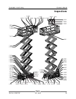
Pre-operation Inspection 


Be sure that the operator’s, safety, and 
responsibilities manuals are complete, legible 
and in the storage container located in the 
platform. 


Be sure that all decals are legible and in place. 
See Inspections section. 


Check for hydraulic oil leaks and proper oil 
level. Add oil if needed. See Maintenance 
section.  


Check for battery fluid leaks and proper fluid 
level. Add distilled water if needed. See 
Maintenance section.  

Check the following components or areas for 
damage, improperly installed, or missing parts and 
unauthorized modifications: 


Electrical components, wiring, and 
electrical cables 


Hydraulic hoses, fittings, cylinders, and 
manifolds 


Drive motors 


Wear pads 


Tires and wheels 


Limit switches, alarms and horn 


Alarms and beacons (if equipped) 


Nuts, bolts and other fasteners 


Brake release components 


Safety arm 


Platform extension 


Scissor pins and retaining fasteners 


Platform control joystick 


Battery pack and connections 


Ground strap 


Platform entry gate 


Pothole guards 


Lanyard anchorage points 


Platform overload components 

Check entire machine for: 


Cracks in welds or structural components 


Dents or damage to machine 


Excessive rust, corrosion or oxidation 


Be sure that all structural and other critical 
components are present and all associated 
fasteners and pins are in place and properly 
tightened. 


Be sure side rails are installed and bolts are 
fastened.  


Be sure that the chassis trays are closed and 
latched and the batteries are properly 
connected. 

Note: If the platform must be raised to inspect the 
machine, make sure the safety arm is in place. 
See Operating Instructions section. 

Summary of Contents for GS-4655

Page 1: ...Operator s Manual Serial Number Range GS 4655 from GS55D 101 AUS Australia with Maintenance Information First Edition First Printing Part No 1294977GT...

Page 2: ...rea Safety 12 Legend 20 Controls 21 Inspections 24 Operating Instructions 36 Transport and Lifting Instructions 44 Maintenance 49 Specifications 51 Copyright 2019 Terex Corporation First Edition First...

Page 3: ...e serial label Serial number stamped on chassis Serial label located on chassis Intended Use and Familiarization Guide The intended use of this machine is to lift personnel including tools and materia...

Page 4: ...ted Area of operation indoor button Area of operation outdoor button Ground controls symbology and related machine movement Lift function enable button Platform up down button Sequential functions and...

Page 5: ...tion indicated in a respective bulletin To view any open bulletins for your machine visit us on the web at www genielift com Contacting the Manufacturer At times it may be necessary to contact Genie W...

Page 6: ...w and understand the safety rules before going on to the next section 2 Always perform a pre operation inspection 3 Always perform function tests prior to use 4 Inspect the workplace 5 Only use the ma...

Page 7: ...use symbols color coding and signal words to identify the following Safety alert symbol used to alert you to potential personal injury hazards Obey all safety messages that follow this symbol to avoi...

Page 8: ...azard Tip over hazard Tip over hazard Electrocution hazard Electrocution hazard Explosion hazard Fire hazard Burn hazard Skin injection hazard Engage safety arm Keep away from moving parts Keep clear...

Page 9: ...Chock the wheels No smoking Grounded AC 3 wire only Replace damaged wires and cords Wheel load Lifting tie down instructions Lifting tie down instructions Lanyard anchorage points Wind speed Tiedown R...

Page 10: ...over hazard Failure to replace batteries with proper weight batteries will result 1292748 A 415 lbs 188 kg DANGER Batteries are used as counterweight and are critical to must weigh 82 lbs 37 kg Batter...

Page 11: ...t 1292960 Collision Hazard Failure to secure machine before releasing brakes will result in death or serious injury 1292960 A DANGER INSTRUCTIONS 1 Make sure machine is on a firm level surface or secu...

Page 12: ...Operator s Manual First Edition First Printing General Safety 10 GS 4655 Part No 1294977GT 1294707 1290655 1293165 44736 28236 1294635...

Page 13: ...all Protection Personal fall protection equipment PFPE is not required when operating this machine If PFPE is required by job site or employer rules the following shall apply All PFPE must comply with...

Page 14: ...t contacts energized power lines Personnel on the ground or in the platform must not touch or operate the machine until energized power lines are shut off Do not operate the machine during lightning o...

Page 15: ...outdoors with the indoor use button selected Indoor Use When raising the platform follow ratings for allowable side force and number of occupants on the next page Do not operate the machine in strong...

Page 16: ...g the battery tray including batteries must weigh a minimum of 188 kg Do not modify or alter a mobile elevating work platform without prior written permission from the manufacturer Mounting attachment...

Page 17: ...conditions with one person in the platform and adequate traction Additional platform weight may reduce slope rating See Driving on a Slope in the Operating Instructions section Fall Hazards The guard...

Page 18: ...e hazards Be aware of crushing hazards when grasping the platform guard rail Observe and use color coded direction arrows on the platform controls and the platform decal plate for drive and steer func...

Page 19: ...in hazardous locations or locations where potentially flammable or explosive gases or particles may be present Damaged Machine Hazards Do not use a damaged or malfunctioning machine Conduct a thorough...

Page 20: ...nals or the cable clamps with tools that may cause sparks Component Damage Hazard Do not use any battery charger greater than 24V to charge the batteries Electrocution Burn Hazards Connect the battery...

Page 21: ...No 1294977GT GS 4655 19 Lockout After Each Use 1 Select a safe parking location firm level surface clear of obstruction and traffic 2 Lower the platform 3 Turn the key switch to the off position and r...

Page 22: ...ort tie down 8 Emergency lowering knob 9 Flashing beacon 10 Steer tire 11 Pothole guard 12 LCD readout 13 Ground controls 14 Brake release switch hydraulic side 15 Non steer tire 16 Entry ladder trans...

Page 23: ...switch for platform off ground selection Turn the key switch to the platform position and the platform controls will operate Turn the key switch to the off position and the machine will be off Turn t...

Page 24: ...ed Emergency Stop button to the on position to operate the machine 2 Lift function button Push this button to activate the lift function 3 Horn button Press the horn button and the horn will sound Rel...

Page 25: ...l and the machine will move in the direction that the blue arrow points Move the control handle in the direction indicated by the yellow arrow on the control panel and the machine will move in the dir...

Page 26: ...is designed to discover if anything is apparently wrong with a machine before the operator performs the function tests The pre operation inspection also serves to determine if routine maintenance pro...

Page 27: ...ds Drive motors Wear pads Tires and wheels Limit switches alarms and horn Alarms and beacons if equipped Nuts bolts and other fasteners Brake release components Safety arm Platform extension Scissor p...

Page 28: ...the machine as it was intended Function Test Fundamentals The function tests are designed to discover any malfunctions before the machine is put into service The operator must follow the step by step...

Page 29: ...audible alarms Descent alarm Lights flash and alarm sounds at 60 flashes beeps per minute Descent delay alarm Lights flash and alarm sounds at 180 flashes beeps per minute Pothole guards not deployed...

Page 30: ...witch to platform control At the Platform Controls Test Emergency Stop 19 Push in the platform red Emergency Stop button to the off position Result No functions should operate Test the Horn 20 Pull ou...

Page 31: ...e control handle in the direction indicated by the yellow arrow Result The platform should lower The descent alarm should sound while the platform is lowering Test the Outdoor and Indoor Use Buttons 3...

Page 32: ...er wheels should turn in the direction indicated by the yellow triangle Test Drive and Braking 46 Press the drive function button 47 Press and hold the function enable switch on the control handle Mac...

Page 33: ...ndicated by the blue arrow then move the control handle in the direction indicated by the yellow arrow Result The drive function should not work in either direction 56 Fully lower the platform 57 Driv...

Page 34: ...ploy 67 Press on the pothole guards on one side and then the other Result The pothole guards should not move 68 Lower the platform Result The pothole guards should return to the stowed position 69 Pla...

Page 35: ...tor determine if the workplace is suitable for safe machine operation It should be performed by the operator prior to moving the machine to the workplace It is the operator s responsibility to read an...

Page 36: ...op 65 1 1281175 Label Lanyard Anchorage Point Fall Restrained 3 1283810 Label Platform Control PanelGS 4655 1 Part No Decal Description Qty 1283878 Label Tech Pro Link 1 1290655 Instructions Maximum S...

Page 37: ...43 52475 82666 1290699 1292746 1292747 1292748 214864 1292275 1290675 1272242 31060 1290668 1292747 72086 82666 1292746 52475 1290699 72086 1292747 1292051 1292746 82666 1263543 1294685 T112804 128081...

Page 38: ...operator s responsibility to follow all the safety rules and instructions in the operator s safety and responsibilities manuals Using the machine for anything other than lifting personnel along with...

Page 39: ...d before operating the machine 2 Turn the key switch to platform control 3 Pull out both ground and platform red Emergency Stop buttons to the on position To Position Platform 1 Press the lift functio...

Page 40: ...ion button again 2 Machines equipped with foot switch Press and hold the foot switch and press and hold the function enable switch on the control handle at the same time 3 Increase speed Slowly move t...

Page 41: ...OR use the following procedure You will need carpenter s level straight piece of wood at least 1 m long tape measure Lay the piece of wood on the slope At the downhill end lay the level on the top edg...

Page 42: ...viewed at the ground controls LCD display Platform Overload If the platform controls LED diagnostic readout displays a flashing OL and the ground controls LCD diagnostic readout displays OL Platform O...

Page 43: ...ne must be taken out of service and charged otherwise all machine functions will be disabled Full Charge Half Charge Low Charge LO Flashing How to Use the Safety Arm 1 Raise the platform approximately...

Page 44: ...orm remove the two front wire lock pins Keep hands free of pinch points 4 Fold the front rail assembly to left side Keep hands clear of pinch points 5 Replace the two removed pins back into each side...

Page 45: ...led water to cover the plates Do not overfill prior to the charge cycle 2 Replace the battery vent caps 3 Connect the battery charger to a grounded AC circuit 4 The charger will indicate when the batt...

Page 46: ...should move the machine on or off the truck The transport vehicle must be parked on a level surface The transport vehicle must be secured to prevent rolling while the machine is being loaded Be sure t...

Page 47: ...4 Open the hydraulic tray 5 Remove the protective cover from the toggle switch 6 Move the toggle switch as indicated in the image to release the brakes The alarm will turn on when the brakes are rele...

Page 48: ...r Transit Always use the extension deck lock when the machine is transported Turn the key switch to the off position and remove the key before transporting Inspect the entire machine for loose or unse...

Page 49: ...achine with a Forklift Be sure the extension deck controls and component trays are secure Remove all loose items on the machine Fully lower the platform The platform must remain lowered during all loa...

Page 50: ...on the machine Determine the center of gravity of your machine using the table and the picture on this page Attach the rigging only to the designated lifting points on the machine There are two 4 4 cm...

Page 51: ...t the beginning of a maintenance procedure it conveys the meaning below Indicates that tools will be required to perform this procedure Indicates that new parts will be required to perform this proced...

Page 52: ...water Note Perform this test after fully charging the batteries 1 Put on protective clothing and eye wear 2 Be sure that the battery cable connections are tight and free of corrosion 3 Be sure that t...

Page 53: ...es not exceed 2 5 m s 2 Highest root mean square value of weighted acceleration to which the whole body is subjected does not exceed 0 5 m s 2 Operating temperature Minimum 29 C Maximum 66 C Airborne...

Page 54: ......

Reviews: