background image

20

Genie  Lift

Part No. 35566

Operator's Manual

First Edition • Sixth Printing

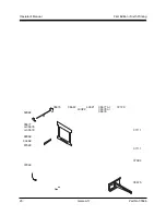
35567

43022

43021

37120

35577

or 35578

or 35579

35577 or

35578 or

35579

35574

97529

37111

37111

37084

35575

33468

82959

52982

37049

Summary of Contents for GL-10

Page 1: ...Operator s Manual First Edition Sixth Printing Part No 35566...

Page 2: ...nts Page Safety 1 Legend 6 Pre operationInspection 8 Function Tests 10 WorkplaceInspection 13 OperatingInstructions 14 Battery Charger Operating Instructions 16 TransportInstructions 17 Load Capacity...

Page 3: ...nd understand the safety rules before going on to the next section 2 Always perform a pre operation inspection 3 Always perform the function tests prior to use 4 Inspect the workplace 5 Only use the m...

Page 4: ...leg casterconfigurationisproperly installed Prior to use check the work area for drop offs holes bumps debris unstable or slippery surfaces or other possible hazardous conditions Avoid debris and une...

Page 5: ...V to 50KV 10 3 1 50KV to 200KV 15 4 6 200KV to 350KV 20 6 1 350KV to 500KV 25 7 6 500KV to 750KV 35 10 7 750KV to 1000KV 45 13 7 Improper Use Hazard Never leave a machine unattended with a load Unauth...

Page 6: ...ks to level the ladder SAFETY RULES Electric Winch Safety Electrocution Hazard Do not operate the DC battery charger unless using a 3 wire grounded extension cord connected to a grounded AC circit Do...

Page 7: ...Legend Genie product decals use symbols color coding and signal words to identify the following Safety alert symbol used to alert personneltopotentialpersonal injury hazards Obey all safety messages t...

Page 8: ...6 Genie Lift PartNo 35566 Operator s Manual First Edition Sixth Printing...

Page 9: ...0 Electric winch battery 31 Electric winch charger 32 Electric winch option 33 Electric winch control 34 Electric winch limit switch 35 Red Emergency Stop button 36 Electric winch control up button St...

Page 10: ...nded Fundamentals The pre operation inspection is a visual inspection performed by the operator prior to each work shift This inspection is designed to discover if anything is apparently wrong with a...

Page 11: ...rs o Cable kinks frays abrasions o Ladder ifequipped o Brake system if equipped o Limit switch electric winch models o Electric winch and related components ifequipped o Hand controls and wiring elect...

Page 12: ...nly use the machine as it was intended Fundamentals The function tests are designed to discover any malfunctions before the machine is put into service The operator must follow the step by step instru...

Page 13: ...ition and be sure the snap pins lock into place Function Tests 1 Select a test area that is firm level and free of obstructions Setup 1 Tilt the machine back 2 Slide each fork onto the carriage and se...

Page 14: ...into the outer frame and then the carriage should lower into the inner frame The carriage and inner frame should move smoothly free of hesitation andbinding Note If the carriage and inner frame do not...

Page 15: ...principles of safe machine operation contained in this operator s manual 1 Avoid hazardous situations 2 Always perform a pre operation inspection 3 Always perform function tests prior to use 4 Inspec...

Page 16: ...o follow all safety rules and instructions in the operator s manual That means every new operator should perform a pre operation inspection function tests and a workplace inspection before using the m...

Page 17: ...achine on stairs using the optional stair glides Moving the machine on stairs without the use of stair glides is not recommended If it is necessary to move the machine on stairs understand and obey th...

Page 18: ...battery reaches full charge 9 Charger models equipped with manual auto selector switch If the ampere meter indicates that the battery is not being charged set the power switch to the MANUAL position...

Page 19: ...actors including but not limited to the physical condition strength and disabilities or prior injuries of the people involved the vertical and horizontal distances the machine has to be moved the numb...

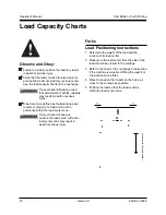
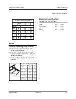
Page 20: ...y of a load and must be positioned within the load center zone Tip over hazard Failure to position the load center within the load center zone may result in death or serious injury Forks Load Position...

Page 21: ...ifting shackle to the desired hole on the boom 12 14 30 35 Model GL 4 500 500 227 227 GL 8 400 400 181 181 GL 10 350 350 159 159 GL 12 350 350 159 159 inches cm lbs kg lbs kg lbs kg lbs kg Rear mounti...

Page 22: ...Genie Lift PartNo 35566 Operator s Manual First Edition Sixth Printing 35567 43022 43021 37120 35577 or 35578 or 35579 35577 or 35578 or 35579 35574 97529 37111 37111 37084 35575 33468 82959 52982 370...

Page 23: ...Genie Lift 21 Operator s Manual First Edition Sixth Printing 97536 97539 82481 82487 97533 97511 or 97512 or 97513 97511 or 97512 or 97513 97532 82487 97540 97540 82487 82487 97510 82962 97539 Serial...

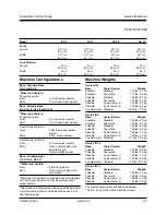
Page 24: ...NA 30 5 cm 30 5 cm Length operating 343 4 in 343 4 in NA NA 88 3 cm 88 3 cm Straddle base Width stowed 283 4 in 283 4 in 283 4 in 283 4 in 73 cm 73 cm 73 cm 73 cm Width extended 431 2 in 431 2 in 431...

Page 25: ...traddle Standard 126 lbs 57 kg Straddle Pneumatic 130 lbs 59 kg Straddle 4 point caster A 137 lbs 62 kg Straddle 4 point caster B 139 lbs 63 kg Counterweight Standard 392 lbs 178 kg Genie Lift 8 Base...

Page 26: ...1 3 3453 6083 Genie Korea Phone 82 25 587 267 Fax 82 25 583 910 Genie Brasil Phone 55 11 41 665 755 Fax 55 11 41 665 754 Genie Holland Phone 31 183 581 102 Fax 31 183 581 566 Genie Scandinavia Phone 4...

Reviews: