background image

LGKSQ    Wireless Key Point Installation Handbook 


Page 8. 

Learn Mode. 
 

The Keypoint must first be learned by the Masthead transceiver and then the Site and 
Sub Net codes must be set otherwise the keypoint will not operate. 
 
The key point transmitter must have the same site and sub net code as the  
masthead.   If PIR detectors are to used as well then they also must have the same site 
and sub net code set on each of them. 
Choose a site code between 1 and 32  and a sub net code from 1 to 8 and set this on the 
masthead.   
For full details on setting up the Masthead see LGIPMT434 installation and operating 
instructions. 


Plug the supplied relay module onto the Masthead transceiver and the learn jumper 
placed onto the two pins as shown in Fig 2. 
 
The power may now be applied.  
The red LED on the module will now flash rapidly indicating that it is ready to learn the 
keypoint. 
 
Now decide on a five digit PIN number which can include  *,#,0 as well as numbers 1-9.  
Also keep a note the Mastheads Site and Sub Net numbers which you will need for the 
next procedure. 
 

Procedure. 
 

Put the keypoint into pairing mode by pressing and holding the STAR button while typing 
3 2 5 6 9 8.  All three lights will now light up. 
 
Let go of the SET button and type a two digit number that represents the site code.   
Blue light lights up. 
 
Now type the Sub Net number (1-8)  If this is successful then all three lights will flash 
simultaneously and a continuous tone will sound.  
As soon as the blue light lights type in the PIN number and press A.  The lights will flash 
alternately and then the red light will light with a continuous tone. 
 
Further key points may be added in the same way.   There is no limit to the number of 
key points that may be learned. 
 
After learning is complete the module jumper must be removed and the power cycled. 
The LED will no longer flash  and will either be ON or OFF depending on the status. 
LED ON is SET and the relay will be closed. 
LED OFF is Un-SET and the relay will be open. 


LGKP  Wireless Key Point Installation Handbook   


Page 5. 

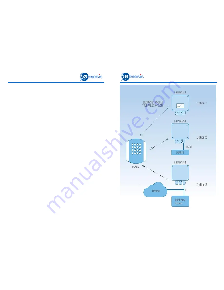
Examples


Fig 1. 

Summary of Contents for LGKSQ

Page 1: ...M16 16 way relay unit with end of line resistor LGRU16ELR 3 versions Relay module with end of line resistor LGRM8ELR 3 versions Optional antenna AE434 Transmitter module LGTX434 Hard wired PIR detectors G1 Wired PIR s 30m x 20m LGHW3020 G1 Wired PIR 15m x 20m LGHW1520 G1 Wired PIR 40m x 4 5m LGHW4004 G1 Wired PIR 12m horizontal curtain LGHW12HC G1 Wired PIR 12m vertical curtain LGHW12VC G2 Wired P...

Page 2: ...ner in the event that a unit has to be returned for any reason Servicing This unit should not require general servicing Any repair work should only be undertaken by Luminite Electronics Ltd Moisture Do not expose the internal electronics of this unit to moisture i e take care during installation not to allow rain or damp into the product When the product is sealed it is water resistant to IP56 Box...

Page 3: ...Installation Handbook Page 10 INDEX page LGKSQ Wireless Key Point Installation Handbook Page 3 Introduction 4 Examples 5 Masthead transceiver 6 Fitting the relay module 5 Preparing the Key Point for use 7 Learn mode 8 Example 9 ...

Page 4: ...et the system There are 248 832 combinations The wireless communication is secure by way of encryption The key point sends a re quest message to the Masthead which responds with a unique encryption key that the key point uses to generate the message Batteries The key point is powered by one PP3 9 volt lithium battery which will provide up to two years of operation with average use Battery not incl...

Page 5: ...include 0 as well as numbers 1 9 Also keep a note the Mastheads Site and Sub Net numbers which you will need for the next procedure Procedure Put the keypoint into pairing mode by pressing and holding the STAR button while typing 3 2 5 6 9 8 All three lights will now light up Let go of the SET button and type a two digit number that represents the site code Blue light lights up Now type the Sub Ne...

Page 6: ... to the masthead Make sure that the power is switched off and simply plug the module onto the 8 way J2 pins as shown in Fig 2 Fig 2 O 1 2 3 4 5 O 6 7 8 9 10 11 O 12 13 14 15 16 Switches 1 5 Site Codes Switches 6 8 Sub Net A Switches 9 11 Sub Net B Switches 12 16 Special Functions Antenna RX TX 0V 9V Learn jumper Power and RS232 Ethernet socket Plug on relay module Mode LED LGKSQ Wireless Key Point...

Reviews: