


INSTALLATION INSTRUCTIONS
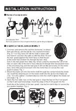
Name of components
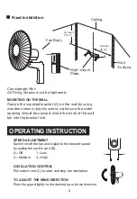
Considerate Hint:
Remove parts from the component before performing installation.
Motor
Rear grill
Lock nut
of grill
Lock nut
of blade
Blade
Front grill
Install by
aligning
3
GUARD & FAN BLADE ASSEMBLY
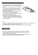
1. Unscrew and remove the spinner clockwise (or obtain
from parts bag), and the plastic nut counterclockwise
(Fig. 2). You may have to hold the shaft in place with
one hand to unscrew the spinner with the other. Mount
the rear guard against the motor face so that the pin
at the motor face bottom fits through the tear drop
hole in the rear guard mounting ring. When correctly mounted the set of two
tabs on each side of the motor face will also fit through their designated holes
in the mounting ring, and the rear guard will rest flat and evenly on the motor
face. Screw the plastic nut back onto the motor face to secure the rear
guard in place. Fig. 1
2. Mount the blade set onto the motor shaft through the center hole in the blade
set. Insert the retaining pin on the motor shaft into the slots in the Blade set
core. Turn the spinner counterclockwise onto the shaft to tighten the blade set
into place. Fig. 3
3. Open the five latch clips on the rear guard. Align the logo on the front guard
so that it will read horizontally. Insert the edge of the front guard into the
fixed clip at the bottom of the rear guard. Use the five latch clips to secure the
two guards together. Fig. 4
Fig.2
Fig.3
Fig.4
Fig.1
Summary of Contents for G16WALL
Page 3: ......