


WARNING! Do not set relative humidity too high during cold
weather. Over humidification can result in condensation,
structural damage and mold. Condensation within a building's
structure can cause loss of structural strength. Condensation
can also enable mold and mildew growth resulting in personal
injury and damage to building structure and contents.
RESIDENTIAL AIR TREATMENT PRODUCTS
Manual humidistat/dehumidistat
control
R
II. APPLICATION
The MHX3 control provides low voltage control of most
humidifiers. The humidistat uses a SPDT switch and is designed
for wall mounting in the living area or mounting on the return air
duct.
RANGE: 10% to 85% RH ELECTRICAL RATING: 30 VAC, 60 VA
OPERATING MODES
The MHX3 can be configured for operation as a standard
humidistat or dehumidistat. When using this product as a
standard humidstat terminals C and NO must be used. Use MHX3
face plate for the humidistat version. When using this product as a
dehumidistat terminals C and NC must be used. Use DHX3 face
plate for the dehumidistat version.
I. SAFETY
WARNING! Improper electrical wiring can result in fire,
failure or loss of humidity control. Disconnect electrical
power before installing and servicing. Failure to disconnect
electrical power may result in injury or death. All local
building and electrical codes must be followed.
The MHX3 humidistat must be installed by a qualified technician.
Failure to properly install the MHX3C may result in property
damage or personal injury.
Homeowners must read instructions and understand the operation
of the MHX3 and the humidifier(s) it controls.
Improper operation can result in over or under humidification.
Over humidification can result in condensation, structural damage
and mold. Condensation within a building's structure can cause
loss of structural strength. Condensation can also enable mold
and mildew growth resulting in personal injury and damage to
building structure and contents.
Safety questions regarding the MHX3 may be directed to General
Filters, Inc. Toll free (866) 476-5101
MHX3
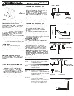
WIRING DIAGRAMS
DIAGRAM 1
WIRING 24V. BYPASS HUMIDIFIER
HUMIDIFIER 24V.
SOLENOID VALVE
OR 24V. DRUM MOTOR
727-58
24 V. TRANSFORMER
(OMIT IF POWER SUPPLY
IS 20-30 VAC)
120V. POWER SUPPLY
SWITCHED WITH FURNACE OPERATION
HMX3
Humidistat
USE TERMINALS C AND NO FOR HUMDISTAT
DIAGRAM 2 WIRING HIGH LIMIT HUMIDISTAT WITH ELITE STEAM HUMIDIFIER
STEAM HUMIDIFIER
CONTROL
MODULE
HUMIDISTAT
N2
GND
N1
AB
AB
GND
IN
NO
C
NC
C
NO
GND
24V
DIAGRAM 3
WIRING 120V. 1137/1000 POWER HUMIDIFIER
HUMIDIFIER CONTROL LEADS
(YELLOW WIRES)
HUMIDISTAT
HUMIDIFIER 24V AUX POWER
(RED WIRES)
(NOT USED, ATTACH WIRE
NUTS TO EACH LEAD)
DO NOT TOUCH TOGETHER!
110V SWITCHED WITH FURNACE HEATING CYCLE
L1
N
G
HUMIDIFIER
POWER CORD
DIAGRAM 4
WIRING 120V. 1137/1000 POWER HUMIDIFIER
HUMIDIFIER 24V AUX POWER
(RED WIRES)
(NOT USED, ATTACH WIRE
NUTS TO EACH LEAD)
DO NOT TOUCH TOGETHER!
110V CONSTANT VOLTAGE
HUMIDIFIER CONTROL LEADS
(YELLOW WIRES)
HUMIDISTAT
110V SWITCHED WITH
FURNACE HEATING CYCLE
FIELD SUPPLIED RELAY
24V COIL, N.O. 5A MIN.
L1
N
L1
N
G
HUMIDIFIER
POWER CORD
727-58
24 V. TRANSFORMER
(OMIT IF POWER
SUPPLY IS 20-30 VAC)
TROUBLESHOOTING -- Humidistat Version
SYMPTOM
DIAGNOSTIC STEPS
Humidifier turns
on and off
repeatedly
1. If mounted on wall, verify wire clearance hole in wall is sufficiently
insulated to preven drafts from affecting the humidistat.
2. If mounted on return air duct, verify humidistat is at least 24”
upstream of humidifiers air discharge.
Humidifier
operates
continuously
1. When the humidity in the home is less than the knob setting on
the humidistat the stat will operate the humidfier until the humidity
is higher. Reduce knob setting.
2. Verify function of solenoid valve.
No humidifier
operation in “ON”
mode
1. Set the thermostat to operate both furnace burner and blower.
Operation may be necessary for system power.
2. Verify terminals 2 and 3 are used on the humidistat. These are the
contacts for humidification.
3. Check voltage at at terminals 2 and 3. There should be no voltage
for an Elite Steam or 1137/1000 power humidifier. Voltage should
be 20-30 VAC from most others.
4. Verify humidifier operation by bypassing the humidistat.
Ideal humidity is
not achieved
1. Technical fault with humidifier. Check water supply, electrical
connnections and condition of the evaporator pad. Verify metering
orifice at the solenoid valve is not obstructed.
2. Humidifier run time is too short. Switch water supply to hot water if
appropriate (use copper tubing).
3. Excess air infiltration. Seal sources of air loss.
4. Humidifier is undersized. Switch water supply to hot water if
appropriate (use copper tubing). Add additional unit(s) or
replace existing unit with a larger unit.
USE TERMINALS C AND NO
FOR HUMDISTAT
DIAGRAM 5
1300 DEHUMIDIFIER
HUMIDISTAT
DH
G2
S1
S2
G1
C
W
Y
D
GENERALAIRE 1300
DEHUMIDIFIER
FORM NO MHX3-06 REV C
WALL MOUNT VERSION
FIG. 1
USE TERMINALS C AND NO FOR HUMDISTAT
USE TERMINALS C AND NO FOR HUMDISTAT
USE TERMINALS C AND NC FOR DEHUMDISTAT
C
NO
NC
C
NO
NC
C
NO
NC
C
NO
NC
C
NO
NC
III. INSTALLATION INSTRUCTIONS - PRECAUTIONS
The installer must be a qualified technician. Disconnect electrical
power before begining installation. Do not install the humidistat
on the warm air duct. Conduct a thorough checkout before leaving
the installation.
WALL MOUNT INSTRUCTIONS - Humidistat/Dehumidistat
versions
1. Choose a location for the MXH3 about five feet above the floor
on an inside wall with average room temperature and relative
humidity conditions.
2. Drill a small hole in the wall and run low voltage wiring to the
location chosen. Pull about 6” of wire through the hole.
Use the entire mounting gasket (both inside and outside
portions) to seal the wall opening or use foam tape to prevent
drafts from affecting the humidistat operation. (see fig 3.)
3. Remove the knob on the humidistat. Squeeze the top and
bottom of the base to release the face of the humidistat.
4. Mount the base horizontally over the wires. Attach directly to
the wall, using the two screws provided in the slotted holes.
5. Connect the wires to the screw terminals on the control assembly
as shown in wiring DIAGRAMS 1-5 Replace face and Knob.
DUCT MOUNTING ON THE RETURN AIR - WALL BASE
Humidistat/Dehumidistat versions (optional)
Do not install the humidistat on the warm air duct or within 48”
of UV light.
1. Locate the humidistat at least 24” upstream of the humidifier or
bypass on the return air duct. Avoid areas of direct radiation like
secondary heat exchanger in the fan compartment.
2. Cut a square in the duct 2-1/4” wide and 1-3/4” tall. Remove the
inner portion of the mounting gasket and discard. Use the outer
portion to seal between the plastic base and the duct. Line up the
base with the cut out and accurately mark the holes thru the plastic
duct mount
plate. (see fig 3.)
3. Revove the humidistat and drill four 3/32” mounting holes.
4. Place the outer portion of the mounting gaskets on the plastic base
and mount the base with four screws. Low voltage wire may enter
the humidistat under the gasket.
5. Connect wires to screw terminals on the control assembly as
shown in wiring DIAGRAMS 1-5. Replace the face and knob.
DUCT MOUNTING ON THE RETURN AIR - DUCT BASE
Humidistat/Dehumidistat versions (recommended)
Do not install the humidistat on the warm air duct or within 48”
of UV light.
1. Locate the humidistat at least 24” upstream of the humidifier
or bypass on the return air duct. Avoid areas of direct radiation
like secondary heat exchanger in the fan compartment.
2. Remove face by inserting screwdriver into the pry slot and
twisting (see fig. 2)
3. Use the plastic duct mount plate as a template. Accurately mark
and drill the (4) 3/32” mounting holes and cut away the 4-1/4” x 2-1/2”
section of the duct mount plate.
4. Place duct mount base gasket on the humidistat base and mount
the base with four screws. Low voltage wire may enter the humidistat
under the gasket (see fig. 2)
5. Connect wires to screw terminals on the control assembly as shown in
wiring DIAGRAMS 1-5. Replace face and knob.
MHX3 CALIBRATION INSTRUCTIONS
(Accurate humidity gauge required)
1. Use an accurate humidity gauge to determine the current relative
humidity in the room where the humidstat is located. This relative
humidity will be used in step 5.
2. Remove the face plate from the housing.
3. Turn the knob on the MHX3 faceplate to the “on” position
4. Very slowly, turn the knob clockwise until you hear a “click” from
the humidistat control and leave the knob in this position.
5. Turn the ring (not the knob) so that the knob is pointed directly
at the current relative humidity number determined in STEP 1.
6. The humidistat in now calibrated to match you humidity gauge.


