

Gas
Liquid
7
A. Solid wire
Str
ip 25 mm (15/16”)
Insulation
Loop
B. Strand wire
Str
ip 10 mm (3/8”)
Round
terminal
Wire
Screw with
special washer
Round terminal
Terminal
board
Wire
Screw with
special washer
Round
terminal
A. For solid core wiring (or F-cable)
(1) Cut the wire end with a wire cutter or wire-cutting pliers, then strip
the insulation to about 25 mm (15/16”) of expose the solid wire.
(2) Using a screwdriver, remove the terminal screw(s) on the terminal
board.
(3) Using pliers, bend the solid wire to form a loop suitable for the
terminal screw.
(4) Shape the loop wire properly, place it on the terminal board and
tighten securely with the terminal screw using a screwdriver.
B. For strand wiring
(1) Cut the wire end with a wire cutter or wire-cutting pliers, then strip
the insulation to about 10 mm (3/8”) of expose the strand wiring.
(2) Using a screwdriver, remove the terminal screw(s) on the terminal
board.
(3) Using a round terminal fastener or pliers, securely clamp a round
terminal to each stripped wire end.
(4) Position the round terminal wire, and replace and tighten the ter-
minal screw using a screwdriver.
Fig. 30
10
5
VACUUMING AND
ADDITIONAL CHARGE
CAUTION
(1) Do not purge the air with refrigerants but use a vacuum
pump to vacuum the installation! There is no extra re-
frigerant in the outdoor unit for air purging!
(2) Use a vacuum pump for R410A exclusively. Using the
same vacuum pump for different refrigerants may dam-
age the vacuum pump or the unit.
1. VACUUM
(1) Remove the cap, and connect the gauge manifold and the vacuum
pump to the charging valve by the service hoses.
(2) Vacuum the indoor unit and the connecting pipes until the pressure
gauge indicates –0.1 MPa (–76 cmHg).
(3) When –0.1 MPa (–76 cmHg) is reached, operate the vacuum pump
for at least 15 minutes.
(4) Disconnect the service hoses and fit the cap to the charging valve to
the specified torque.
(5) Remove the blank caps, and fully open the spindles of the 2-way and
3-way valves with a hexagon wrench (Torque : 6 to 7 N · m (60 to 70
kgf · cm).
(6) Tighten the blank caps of the 2-way valve and 3-way valve to the
specified torque.
Table 6
Fig. 29
Connecting pipe
Blank cap
Hexagon wrench
3-way valve
Charging port
Cap
Service hose
with valve core
Outdoor unit
2. ADDITIONAL CHARGE
Refrigerant suitable for a piping length of 7.5 m is charged in the outdoor
unit at the factory.
When the piping is longer than 7.5 m, additional charging is necessary.
For the additional amount, see the table below.
Table 7
CAUTION
(1) When moving and installing the air conditioner, do not
mix gas other than the specified refrigerant (R410A)
inside the refrigerant cycle.
(2) When charging the refrigerant R410A, always use an
electronic balance for refrigerant charging (to meas-
ure the refrigerant by weight).
(3) When charging the refrigerant, take
into account the slight change in
the composition of the gas and liq-
uid phases, and always charge from
the liquid phase side whose com-
position is stable.
(4) Add refrigerant from the charging valve after the com-
pletion of the work.
(5) If the units are further apart than the maximum pipe
length, correct operation can not be guaranteed.
14
CUSTOMER GUIDANCE
Explain the following to the customer in accordance with the operating
manual:
(1) Starting and stopping method, operation switching, temperature ad-
justment, timer, air flow switching, and other remote controller opera-
tions.
(2) Air filter removal and cleaning, and how to use the air louvers.
(3) Give the operating and installation manuals to the customer.
(4) If the signal code is changed, explain to the customer how it changed
(the system returns to signal code A when the batteries in the remote
controller are replaced).
1. REMOTE CONTROLLER HOLDER
INSTALLATION
•
Install the remote controller with a distance of 7 m between the remote
controller and the photocell as the criteria. However, when installing
the remote controller, check that it operates positively.
•
Install the remote controller holder to a wall, pillar, etc. with the tapping
screw (Fig. 48).
PART NO. 9373244011-03
13
Fig. 48
REMOTE CONTROLLER
INSTALLATION
CAUTION
(1) Check that the indoor unit correctly receives the sig-
nal from the remote controller, then install the remote
controller holder.
(2) Select the remote controller holder selection site by
paying careful attention to the following:
Avoid places in direct sunlight.
Select a place that will not be affected by the heat from
a stove, etc.
1
Set
Remote Controller
holder fixing
Remote Controller
mounting
2
Push
Remote
controller
Tapping
screw
(small)
Remote controller
holder
2. SWITCHING REMOTE CONTROLLER SIGNAL
CODES
•
Air conditioner settings
Fig. 49
Indoor unit
Printed circuit board
Table 10
Jumper wire
JM3
Connect
Disconnect
Connect
Disconnect
Remote controller
signal code
A (Primary setting)
B
C
D
JM2
Connect
Connect
Disconnect
Disconnect
•
Confirm the setting of the remote controller signal code and the printed
circuit board setting.
If these are not confirmed, the remote controller cannot be used to op-
erate for the air conditioner.
•
Remote controller settings
(1) Press the START/STOP button and display only the clock.
Fig. 50
(2) Press the MASTER CONTROL button continuously for more than 5
seconds to display the current signal code.
Fig. 51
(3) Change the signal code with the
button (
).
Fig. 52
(4) Press the MASTER CONTROL button again to return to the clock
display and change the signal code.
12
Blank cap (2-way valve)
Blank cap (3-way valve)
Charging port cap
Tightening torque
20 to 25 N · m (200 to 250 kgf · cm)
25 to 30 N · m (250 to 300 kgf · cm)
10 to 12 N · m (100 to 120 kgf · cm)
Use a 4 mm
hexagon wrench.
R410A
6
GAS LEAKAGE INSPECTION
CAUTION
After connecting the piping, check the joints for gas leak-
age with gas leak detector.
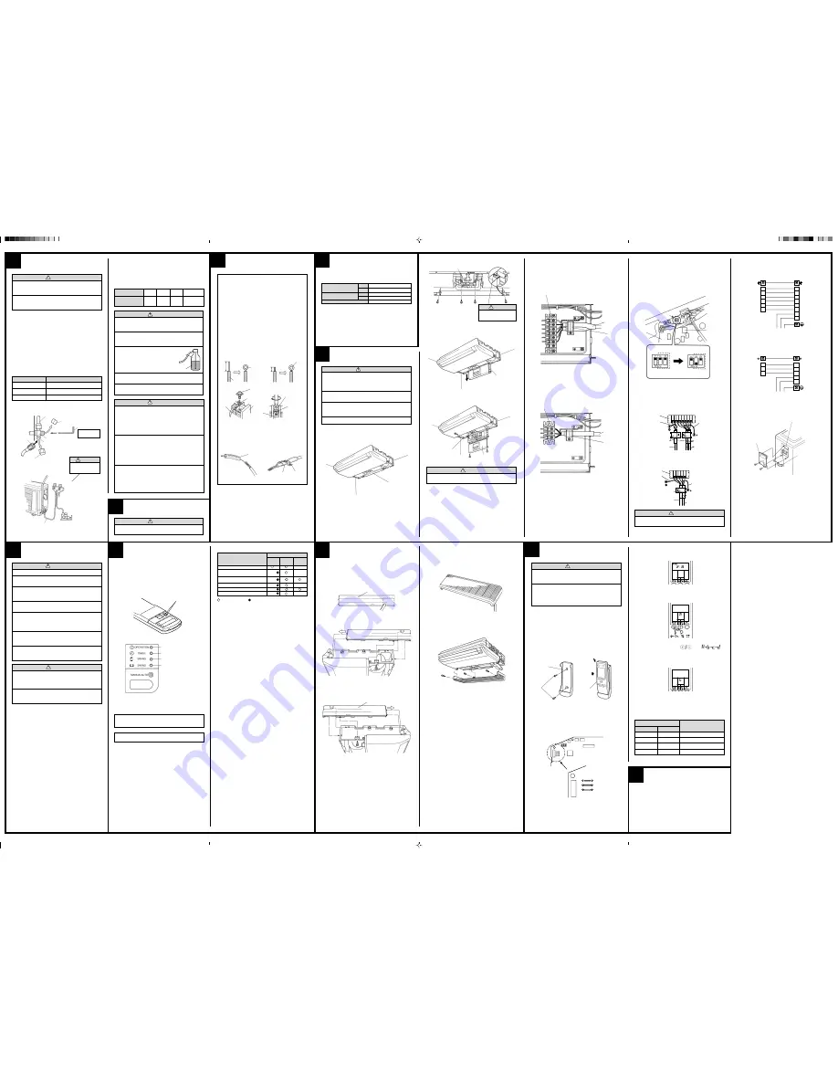
HOW TO CONNECT WIRING
TO THE TERMINALS
HOW TO FIXED CONNECTION CABLE AND
POWER CABLE AT THE CABLE CLAMP
After passing the connection cable and power cable through the insu-
lation tube, fasten it with the cable clamp.
Fig. 31
Use VW-1, 0.5 to 1.0 mm thick, PVC tube as the insulation tube.
Insulation tube
Insulation tube
Cable clamp
ELECTRICAL REQUIREMENT
•••••
Electric wire size and fuse capacity:
•••••
Install the disconnect device with a contact gap of at least 3 mm nearby
the units. (Both indoor unit and outdoor unit)
•••••
Always make the air conditioner power supply a special branch circuit
and provide a special breaker.
•••••
Always use H07RN-F or equivalent as the power supply cable and the
connection cable.
Table 8
8
ELECTRICAL WIRING
CAUTION
(1) Match the terminal block numbers and connection ca-
ble colors with those of the outdoor unit.
Erroneous wiring may cause burning of the electric
parts.
(2) Connect the connection cables firmly to the terminal
block. Imperfect installation may cause a fire.
(3) Always fasten the outside covering of the connection
cable with the cable clamp. (If the insulator is chafed,
electric leakage may occur.)
(4) Always connect the ground wire.
9
1. INDOOR UNIT SIDE
(1) Remove the electric component box.
Fig. 32
Electric component box
Fig. 33
Electric component box
Remove the four
tapping screws.
(2) Pull out the electric component box.
Fig. 34
Electric component box
(3) Remove the electric component box cover.
Fig. 35
CAUTION
Do not remove the screws. If the
stays are removed, the electric
component box will fall.
Electric component box cover
Remove the three tapping screws.
CAUTION
Be careful not to pinch the lead wires between the electric
component box and base.
Base
(4) Wiring
[Heat & Cool model (Reverse cycle)]
1
Remove the cable clamp.
2
Process the end of the connection cables to the dimensions shown in
Fig. 36.
3
Connect the end of the connection cable fully into the terminal block.
Fig. 36
4
Fasten the connection cable with a cable clamp.
5
Fasten the end of the connection cable with the screw.
Cable clamp
Terminal block
Connection
cable
[Cooling model]
1
Remove the cable clamp.
2
Process the end of the connection cables to the dimensions shown in
Fig. 37.
3
Connect the end of the connection cable fully into the terminal block.
Fig. 37
4
Fasten the connection cable with a cable clamp.
5
Fasten the end of the connection cable with the screw.
Cable clamp
Terminal block
Connection
cable
(5) Floor console/Under ceiling select switch
1
The electrical circuits for this were set for use as a ceiling type at the
factory.
2
The following changes must be made to the settings if the unit is to be
used as a floor type.
3
Changing the settings for the electrical circuits.
Switch 1 (SW1) on the printed circuit board inside the electric compo-
nent box must be set as follows.
Fig. 38
SW1
SW1
Under ceiling type
Floor console type
2. OUTDOOR UNIT SIDE
Fig. 39
Fig. 40
2
(N)
1
(L)
3
N
L
2
(N)
3
1
(L)
2
(N)
1
(L)
3
4
5
6
2
(N)
1
(L)
N
L
3
4
5
6
3. INSTALL THE TERMINAL COVER
Fig. 41
Cooling model
Connection cable
Green/Yellow
Indoor unit
side terminal
Power supply
Outdoor unit
side terminal
Heat & Cool model
(Reverse cycle)
Connection cable
Green/Yellow
Indoor unit
side terminal
Power supply
Outdoor unit
side terminal
POWER
WARNING
(1) The rated voltage of this product is 230V A.C. 50Hz.
(2) Before turning on the verify that the voltage is within
the 198V to 264V range.
(3) Always use a special branch circuit and install a spe-
cial receptacle to supply power to the room air condi-
tioner.
(4) Use a circuit breaker and receptacle matched to the
capacity of the room air conditioner.
(5) The circuit breaker is installed in the permanent wir-
ing. Always use a circuit that can trip all the poles of
the wiring and has an isolation distance of at least
3 mm between the contacts of each pole.
(6) Perform wiring work in accordance with standards so
that the room air conditioner can be operated safely
and positively.
(7) Install a leakage circuit breaker in accordance with the
related laws and regulations and electric company
standards.
CAUTION
(1) The power source capacity must be the sum of the room
air conditioner current and the current of other electri-
cal appliances. When the current contracted capacity
is insufficient, change the contracted capacity.
(2) When the voltage is low and the air conditioner is diffi-
cult to start, contact the power company the voltage
raised.
11
CHECK ITEMS
(1) INDOOR UNIT
(1) Is operation of each button on the remote controller normal?
(2) Does each lamp light normally?
(3) Do not air flow direction louvers operate normally?
(4) Is the drain normal?
(5) Is there any error noise and vibration during operation?
(2) OUTDOOR UNIT
(1) Is there any error noise and vibration during operation?
(2) Will noise, wind, or drain water from the unit disturb the neighbors?
(3) Is there any gas leakage?
•
Do not operate the air conditioner in the test running state for a long
time.
•
For the operation method, refer to the operating manual and perform
operation check.
TEST RUNNING
•
Perform test operation and check items 1 and 2 below.
•
For the operation method, refer to the operating manual.
•
The outdoor unit may not run, depending on the room temperature.
In this case, the ‘TEST RUN’ signal is received during air conditioner
operation (use a metallic object to short the two metal contacts under
the battery compartment lid and send the ‘TEST RUN’ signal from the
remote controller).
Fig. 42
Operation can be checked by lighting and flashing of the display section
OPERATION and TIMER lamps.
Perform judgment in accordance with the following.
•
Test running
When the air conditioner is run by pressing the remote controller test
run button, the OPERATION and TIMER lamps flash slowly at the
same time.
•
Error
The OPERATION, TIMER and SWING lamps operate as follows (Ta-
ble 9) according to the error contents.
Short the two metal contacts under
the battery compartment lid.
OPERATION lamp (Red)
TIMER lamp (Green)
SWING lamp (Orange)
SWING lamp (Orange)
Table 9
MOUNT THE COVER PLATE
AND THE INTAKE GRILLE
1. MOUNT THE COVER PLATE (RIGHT)
(1) Cut a pipe exit hole in the right plate. This is only when the pipe exits
from the right side. (This operation is not required when the protru-
sion is on the top or rear.)
Fig. 43
(2) Join the cover plates (right) and mount with screws (Fig. 44).
Fig. 44
Cover plate (Right)
2. MOUNT THE COVER PLATE (LEFT)
(1) Join the cover plates (left) and mount with screws.
Fig. 45
3. MOUNT THE INTAKE GRILLE
(1) Cut the right side of the intake grille. This is only when the pipe exits
from the right side (Fig. 46).
Fig. 46
Cover plate (Left)
(2) Insert the hinges on the bottom of the intake grille into the holes in the
base assembly. Then mount the arms to the 3 areas on the top of the
intake grille (Fig. 47).
Fig. 47
SW1
Microcomputer
JM1 (A)
JM2 (R1)
JM3 (R2)
Printed circuit
board
Error contents
Error display
OPERATION
TIMER
SWING
(RED)
(GREEN) (ORANGE)
—
2 times
—
2 times
3 times
—
3 times
6 times
—
: Fast flashing
: Slow flashing
— : Off
Indoor unit circuit board error
Indoor unit room temperature sensor
opened
Indoor unit room temperature sensor
short circuited
Indoor unit piping sensor opened
Indoor unit piping sensor short circuited
Indoor unit fan error
CAUTION
Use a clean gauge mani-
fold and charging hose
for R410A exclusively.
t
Gauge manifold
Vacuum pump
Service hose
Additional
refrigerant
7.5 m
(25 ft)
None
Pipe length
10 m
(33 ft)
37.5 g
(1.3 oz)
15 m
(49 ft)
112.5 g
(4.0 oz)
15 g/1 m
(0.53 oz/3.3 ft)
Power supply cable (mm
2
)
Connection cable (mm
2
)
Fuse capacity (A)
MAX.
MIN.
MAX.
MIN.
3.0
2.0
2.5
1.5
15
[Cooling model]
N
L
1
(L)
2
(N)
3
N
L
1
(L)
2
(N)
3 4 5 6
Terminal block
Cable clamp
Insulation tube
Connection cable
Power supply cable
Ground wire length
65 mm or over
[Heat & Cool model (Reverse cycle)]
Terminal block
Cable clamp
Insulation tube
Connection cable
Power supply cable
Control box
Ground wire length
80 mm or over
Ground wire length
45 mm or over
Control box
Ground wire length
65 mm or over
CAUTION
When routing the ground wires, leave slack as shown in
the illustrations.
Cable clamp
Terminal cover
Terminal block
WARNING
(1) During installation, make sure that the refrigerant pipe
is attached firmly before you run the compressor.
Do not operate the compressor under the condition of
refrigerant piping not attached properly with 2-way or
3-way valve open.
This may cause abnormal pressure in the refrigeration
cycle that leads to breakage and even injury.
(2) During the pump-down operation, make sure that the
compressor is turned off before you remove the
refrigerant piping.
Do not remove the connection pipe while the compressor
is in operation with 2-way or 3-way valve open.
This may cause abnormal pressure in the refrigeration
cycle that leads to breakage and even injury.
(3) When installing and relocating the air conditioner, do
not mix gases other than the specified refrigerant
(R410A) to enter the refrigerant cycle.
If air or other gas enters the refrigerant cycle, the pressure
inside the cycle will rise to an abnormally high value and
cause breakage, injury, etc.
9373244011-03_IM_back.p65
23/9/2011, 10:23 AM
1


