background image

NOTE


This saw is intended for use with 10" (250mm) diameter or less saw blades having a center hole diameter of 

5/8". 

There are many types of blades available to perform specific cutting jobs, such as crosscuts or ripping 

only, or tor 

use 

with plywood, paneling and other products. A good quality specialty blade can produce a finer 

finish, be more efficient and place less strain 

on 

the saw. Use only saw blades designed for 

use 

at a maxi- mum 

operating speed of 

6000 RPM 

or less. Saw blades should be kept clean and sharp. Never store saw blades 

by stacking them directly in contact with each other

Place a layer of cardboard or similar material between 

the blades to keep them from coming into contact with each other.


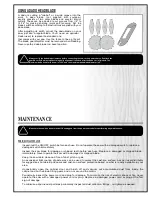
ATTACH THE BACK FENCE RAIL TO YOUR SAW


Referring to the diagram above

place hex

head bolts and  where applicable lock washers and nuts to  assemble 

the rear rail to the back of the saw.


INSTALL AND ALIGN THE FENCE


Proceed to fence installation and  alignment as per the instructions provided in your fence manual.


REMOVE / INSTALL A SAW BLADE


                                                    Be sure the saw is unplugged and completely disconnected whenever installing or removing a saw blade!


REMOVE A SAW BLADE


LOOSEN


1.


Remove the table insert

.


8


          Holding the arbor  with the  arbor  wrench provided,


,


                                                                                                              wedge a  block  of  wood between the teeth in front                                                                                                                                                                                                                                 


                                                                                                                               of the saw and  pull the arbor wrench toward you or                           


counterclockwise


Summary of Contents for 850-3

Page 1: ...dustrial motor 3HP 1PH 5HP 3PH High precision General T Fence system with 52 and 36 long guide rails 2 miter gauge T slots and deluxe cast iron miter gauge Magnetic emergency stop safety switch to prevent unwanted or unintentional start up Matching dual V belt drive on balanced cast iron pulleys for smooth vibration free running Arbor mounted on heavy duty permanently lubricated sealed ball bearin...

Page 2: ...is manual before assembling installing and operating the unit The manual s purpose is to familiarize you with the safe operation basic function and features of this saw as well as the set up maintenance and identification of its parts and components This manual is not intended as a substitute for formal woodworking instruction nor to offer the user instruction in the craft of woodworking If you ar...

Page 3: ... file a Claim To file a claim under our Standard 3 year Limited Warranty or under our Limited Lifetime Warranty all defective parts components or machinery must be returned freight or postage prepaid to General International or to a nearby distributor repair center or other location designated by General International For further details call our service department at l 888 664 0449 or your local ...

Page 4: ...nstall a saw blade 12 Level the table insert 12 Connecting toadust collector 13 BASIC ADJUSTMENTS AND CONTROLS 13 Connecting to a power source 13 ON OFF magnetic power switch 13 Overload protection 14 Blade height adjustment 15 Blade tilt bevel adjustment 15 OPERATING INSTRUCTIONS 15 Typesof cuts 16 Ripping 16 Bevel ripping 16 Ripping small work pieces 16 Cross cutting 17 Bevel cross cutting 17 7 ...

Page 5: ...ead to accidents 13 If using a power feeder stop the feeder before stop ping the table saw 14 Do not push or force stock into the blade The saw will perform better and more safely when working at the rate for which it was designed 15 Use suitable support when cutting stock that does not have a flat surface Always hold stock firmly against the fence when ripping or against the miter gauge when cros...

Page 6: ...ips or the fuse blows reg ula rly your machine may be operating on a circuit that is close to its amperage draw capacity However if an unusual amperage draw does not exist and a power failure still occurs contact a qualified technician or our service department EXTENSION CORDS The use of an extension cord is not generally recommended for 230V equipment If you find it necessary use only 3 wire exte...

Page 7: ...o table insert can be purchased through your General MFG General International distributor To encourage safety through the proper use of either the supplied riving style splitter blade guard assembly or the European style riving knife the 850 saw has been designed with a quick install quick release feature allowing the user to install or remove either of these safety components in seconds UNPACKIN...

Page 8: ...jury to either the operator or the shop visitor It is advisable to take a few moments to either paint using non slip paint or using tape define on the floor the limits or perimeter of each machine s safety zone Take steps to ensure that all operators and shop visitors are aware that these areas are off limits whenever a machine is running for everyone but the individual operating the unit CLEAN UP...

Page 9: ... the machine to the power source verify that the voltage of your power supply corresponds with the Voltage specified on the motor ID nameplate This tool is for INDOOR use ONLY Do NOT use in wet or damp locations INSTALL AND ADJUST RAILS AND FENCE ATTACHTHEFRONTFENCERAILTOYOUR SAW Referring to the diagram above place 4 flat head countersunk screws lock washers and nuts to assemble the front rail to...

Page 10: ...ach other Place a layer of cardboard or similar material between the blades to keep them from coming into contact with each other ATTACHTHEBACKFENCERAIL TOYOUR SAW Referring to the diagram above place hex head bolts and where applicable lock washers and nuts to assemble the rear rail to the back of the saw INSTALL AND ALIGN THEFENCE Proceed to fence installation and alignment as per the instructio...

Page 11: ... 2 Replace the flange and arbor nut Holding the arbor with the arbor wrench provided wedge a block of wood between the teeth at the rear of the saw and push the arbor wrench away from you or clockwise 3 Re install the table insert TOINSTALL ASAWBLADE 1 Install the blade on the arbor so that the openings between the teeth face the front of the saw the blade spins in the counterclockwise direction L...

Page 12: ...lector before starting the saw always stop the saw before turning off dust collector BASIC ADJUSTMENT CONTROLS To avoid the risk of shock or fire do NOT operate the unit with a damaged power cord or plug Replace damaged plug or cord Immediately Once the assembly steps have been completed plug the power cord into an appropriate outlet Refer back to the section entitled ELECTRICAL REQUIREMENTS and m...

Page 13: ...n at the beginning of this manual 3 Overworked circuit caused by operating on a circuit that is close to its amperage draw capacity Make sure the circuit being used is capable of handling the amperage draw from this machine as well as any other electrical devices operating on the same circuit If you are unsure consult a qualified electrician To reset the overload protection switch after it has bee...

Page 14: ... are tight If ripping make sure the fence lock lever is engaged and that the fence is parallel to the blade If cross cutting make sure the miter gauge is locked tight While using the saw be sure to wear safety glasses at all times Make sure that the blade guard splitter assembly is properly installed and aligned with the blade and that the anti kickback pawls are functioning ...

Page 15: ...er remain on the table tilt up to be caught on the end of the guard or fall onto the floor or outfeed table The waste part of the stock remains on the table to be removed only after the saw is stopped unless it is large enough for immediate safe removal If the work to be ripped is narrow it is safer to use a push stick rather than the hands to feed it into the blade Push sticks with non slip gripp...

Page 16: ...ay from the turning blade Turn off the motor BEVELCROSS CUTTING Bevel angle verify the alignment of the guard and splitter and verify that there is clearance with the saw blade ADJUSTING AND USING THE MITER GAUGE ADJUSTING THEMITER GAUGE index stops at 90 and 45 to the right and left with a 30 maximum To use a setting other than 90 loosen the lock knob by turning it counter clockwise flip down the...

Page 17: ...ood If you measure a cut for 24 inches line up the blade on the waste side of the mark Don t cut through the middle of the measurement line or you ll reduce your desired board length by half the width of the saw blade For accurate work don t mark your cut with a fat pencil line A narrow dash with a sharp pencil point is best Encircle the dash so you ll find it again and add a small X to indicate t...

Page 18: ...s been turned off unplugged from the power source before performing any maintenance PERIODIC MAINTENANCE Inspect test the ON OFF switch before each use Do not operate the saw with a damaged switch replace a damaged switch immediately Inspect the saw blade for damage or chipped teeth before each use Replace a damaged or chipped blade immediately Never operate the saw with a damaged or chipped blade...

Page 19: ...t as needed Note To lubricate the blade tilt mechanism apply a very light dab of any all purpose grease available at any hardware store To lubricate the blade height adjustment mechanism loosen and remove the lock knob on the blade tilt adjustment hand wheel then spray some dry lubricant into the hole8 The motor and all bearings are sealed and permanently lubricated no further lubrication is requi...

Page 20: ...MODEL 850 3 850 5 3 GENERAL INTERNATIONAL GENERAL INTERNATIONAL POWER PRODUCTS LLC 6243 Industrial Parkway I Whitehouse Ohio 43571 USA ...

Page 21: ......

Page 22: ......

Page 23: ...IMPORTANT When ordered replacement parts always give the Model number serial number part number ...

Reviews: