background image

There is a 2” diameter dust outlet on the rear of the machine 
allowing for the connection to a dust collector 

(not included).

A 2” TO 4” DUST HOSE ADAPTOR is also included to facilitate 
(if needed) connection to a standard 4” dust collection 
hose.

Be sure to use appropriate size hose and fittings 

(not included).

and check that all connections are sealed tightly to mini-
mize airborne dust.

If you do not already own a dust collection system consi-
der contacting your GENERAL® INTERNATIONAL distributor 
for information on our complete line of dust collection 
systems or visit our Web Site at: www.general.ca 

Before sanding connect the machine to a dust 
collection system.

Always turn on the dust collector before starting the
sander and always stop the sander before turning
off the dust collector.

CONNECT TO A DUST COLLECTOR

OPERATING INSTRUCTIONS 

BASIC FUNCTIONS OF THIS MACHINE

This machine has been designed for sanding or polishing round or curved surfaces on wood, plastic, or metal 
materials. It is ideal for use in smaller woodworking projects in a hobbyist/home shop environment. This machine is not
designed with a continuous duty rating or for industrial applications.

CONNECTING TO A POWER SOURCE

Plug the machine into a proper receptacle – before connecting to the power source make sure that the switch is in
the “off” position and that the power supply is of the same type as that stamped on the I.D. nameplate of the motor.
Running on low voltage will damage the motor.

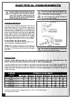
To avoid risk of shock or fire do not operate the unit with a damaged power cord or plug. Replace damaged cord
or plug immediately.

ON/OFF SWITCH & SAFETY PIN

The switch assembly is equipped with a lock-out safety pin.
When the pin is installed through the green “on” button, the
machine cannot be started.

To start the machine, lift the red stop switch panel and remove
the lock-out pin. Lower the stop panel and push the green “ON”
button. Wait for the spindle to reach full speed before sanding.

To stop the machine, push on the RED “STOP” panel and wait for
the spindle to come to a complete stop.

When you have finished using the machine be sure to re-install
the lock-out pin and unplug the machine from the power
source.

12

Summary of Contents for 15-220

Page 1: ...aper 1 1 2 2 spindles come with rubber drums Includes 4 table inserts to accomodate different spindle sizes OSCILLATIONS PER MINUTE 29 LENGTH OF OSCILLATION 15 16 24 mm TABLE SIZE 14 1 2 x 14 1 2 368...

Page 2: ...d of 24 months from date of purchase any genuine part or parts which upon examination prove to be defective in work manship or material In order to obtain this warranty all defective parts must be ret...

Page 3: ...tenance or spindle changes make sure it is properly re installed before re starting the machine 15 Hold the workpiece firmly against the table and use suitable support if the workpiece does not have a...

Page 4: ...ell as damage to the machine If in doubt contact a qualified electrician before connecting to the power source EXTENSION CORDS USE ONLY 3 WIRE EXTENSION CORDS THAT HAVE 3 PRONG GROUNDING PLUGS AND 3 P...

Page 5: ...VERTICAL OSCILLATING SPINDLE SANDER 15 220 IDENTIFICATION OF MAIN PARTS AND COMPONENTS ACCESSORY STORAGE BASE CAST IRON TABLE SWITCH ASSEMBLY TABLE INSERT TABLE TILT LOCK LEVER SANDING SPINDLE 5...

Page 6: ...ding sleeve 5 8 1 Sanding sleeve 1 2 1 Sanding sleeve 1 4 1 Spindle 5 8 1 Spindle 1 2 1 Spindle 1 4 1 TABLE INSERT 2 oblong 1 TABLE INSERT 3 4 oblong 1 TABLE INSERT 3 4 round Mounted on the machine 1...

Page 7: ...e you clean all metal surfaces of the spindles with a mild solvent or kerosene To prevent rust apply a light coating of paste wax or regular applications of General International Top Saver item GC 010...

Page 8: ...that the sleeve is now on the spindle securely by pulling on the sleeve to make sure it does not slide off the spindle Step 4 For the 1 1 2 and 2 spindles slide the sleeve onto the spindle Step 5 Usin...

Page 9: ...unplugged Step 1 Select the desired spindle and while holding the spindle seat in place with a 17 mm wrench screw the threaded end into the spindle seat counter clockwise reverse threads until hand t...

Page 10: ...plains which inserts can be used for different diameter spindles FAILURE TO USE THE PROPER INSERT WITH THE CORRESPONDING SPINDLE MAY RESULT IN INJURY AND OR DAMAGE TO THE MACHINE OR THE WORKPIECE SPIN...

Page 11: ...ee the accompanying SELECTION GUIDE page 10 to select the correct TABLE INSERT for the spindle being used 2 Loosen both locking levers and tilt the table until the pointer is at the desired angle 3 Ho...

Page 12: ...is ideal for use in smaller woodworking projects in a hobbyist home shop environment This machine is not designed with a continuous duty rating or for industrial applications CONNECTING TO A POWER SOU...

Page 13: ...Make sure the table tilt locking levers are secured and that the table is locked in place at the desired angle or tilt 7 Always loosen both table tilt locking levers before changing the angle position...

Page 14: ...1 4 X 6 120 Grit 15 211F Sanding Sleeve 1 4 X 6 150 Grit 15 212A Sanding Sleeve 1 2 X 6 40 Grit 15 212B Sanding Sleeve 1 2 X 6 60 Grit 15 212C Sanding Sleeve 1 2 X 6 80 Grit 15 212D Sanding Sleeve 1...

Page 15: ...15 Mod le 15 220...

Page 16: ...06006 BEARING 6006ZZ 1 15220 24 S0520059 RETAINING RING C TYPE 1 15220 25 30202005 CONNECTING ROD NUT 4 15220 26 S0050506M SET SCREW M5 X 0 8 X 6L 2 15220 27 S05ETW04 RETAINING RING E TYPE 2 15220 28...

Page 17: ...220 73 SEE LIST ON PG 14 FOR OPTIONAL REPLACEMENT SANDING SLEEVES 15220 74 SEE LIST ON PG 14 FOR OPTIONAL REPLACEMENT SANDING SLEEVES 15220 75 SEE LIST ON PG 14 FOR OPTIONAL REPLACEMENT SANDING SLEEVE...

Page 18: ...serial number of the machine and part number Also a brief description of each item and quantity desired 15 220 8360 Champ d Eau Montreal Quebec Canada H1P 1Y3 Tel 514 326 1161 Fax 514 326 5565 Parts S...

Reviews: