background image

14

General International

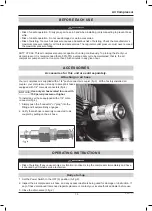
4.  Connect the air hose to the quick connect socket on the regulator assembly by inserting the quick connect 

plug on the air hose into the quick connect socket. The quick connect socket collar will snap forward and 

lock the plug into place, providing an air tight seal between the socket and plug. To release the air hose, 

push the collar back on the quick connect socket.

5. 

Firmly grasp the hose prior to inserting it into the quick connect and when removing it from the quick 

connect socket.

6.  Plug the power cord into the proper receptacle.
7. 

Move the Power Switch to the ON (I) position (pull it up) and the compressor pump will start, building 

pressure in the tank until cut-out pressure is reached and the unit shuts off automatically (A).

8. 

Adjust the regulator to a psi setting that is needed for your application and be sure it is within the 

safety standards required to perform the task. If using a pneumatic tool, the manufacturer should have 

recommendations in the manual for that particular tool on operating psi settings.

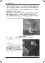
Drain Valve


Make 

sure the tank drainage valve (fig.5) is closed and not in the open position.

Pressure Switch

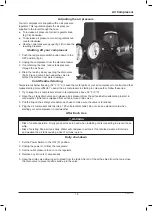
1.  Check that the red pressure switch button is pushed down to the OFF position (fig 6)

.

2.  Ensure that the power supply you are going to use 

is operating normally.

3.  Insert the power supply cord into the power supply 

socket. 

4. 

Turn the pressure switch on, pulling the red button 

up to the ON position.

5.  On the tank pressure gauge fig.2C), you can watch 

pressure build in the tank until the pump stops at 

the factory-set pressure, about 115 to 125 psi.

6. 

This first time running your compressor and 

periodically thereafter, check for air leaks. If the 

gauge indicates pressure is going down in the tank 

or you hear leakage, you could apply soapy water 

to all joints in the air transport piping. Tighten these 

joints if bubbles form.

fig.5

fig.6

Summary of Contents for AC1220

Page 1: ... Owner s Manual WARNING Read carefully and understand all ASSEMBLY AND OPERATION INSTRUCTIONS before operating Failure to follow the safety rules and other basic safety precautions may result in serious personal injury Model AC1220 READ AND SAVE THESE INSTRUCTIONS ...

Page 2: ... unit as it was supplied from the factory at the time of printing Because we are committed to making constant improvements General International reserves the right to make changes to components parts or features of this unit as deemed necessary without prior notice and without obligation to install any such changes on previously delivered units Reasonable care is taken at the factory to ensure tha...

Page 3: ...ounding 8 Grounded Tools Tools with 3 Prong Plugs 8 Extension Cords 8 Main Parts of Air Compressor 11 Getting Started 12 Assembly 12 Pre Operation 12 Before operating your air compressor 12 General Overview 12 Installation and Location 12 Before Each Use 13 Accessories 13 Accessories for this unit are sold separately 13 Operating Instructions 13 Drain Valve 14 Pressure Switch 14 Adjusting the air ...

Page 4: ...m Branch Circuit Requirement 15 Amps Fuse Type Time Delay Air Tank Capacity Vertical 20 gallons 75 7 liters Motor Speed 3 400 RPM Maximum Operating Air Pressure 125 psi Maximum Tank Air Pressure 150 psi CFM 40 psi 4 18 CFM 90 psi 2 31 Fill Time 0 psi To 40 psi 1 Minute 47 Seconds Fill Time 0 psi To 90 psi 6 Minutes 47 Seconds Fill Time 0 psi To 125 psi 10 Minutes 35 Seconds Recovery Time 90 125 ps...

Page 5: ...t in injury Using the product in confined work areas may put you dangerously close to cutting tools and rotating parts Do not use the product where there is a risk of causing a fire or an explosion e g in the presence of flammable liquids gases or dust The product can create sparks which may ignite the flammable liquids gases or dust Do not allow the product to come into contact with an electrical...

Page 6: ...or animals CAUTION Air Compressor Use And Care Do not force the air compressor Products are safer and do a better job when used in the manner for which they are designed Plan your work and use the correct product for the job Check for damaged parts before each use Carefully check that the product will operate properly and perform its intended function Replace damaged or worn parts immediately Neve...

Page 7: ...ngs accordingly DO NOT exceed manufacturer s rated safe operating pressures for these items Make sure all hose connections are adequately secured to prevent tools or hose ends from being accidentally disconnected Remove adjusting keys or wrenches before turning the tool on A wrench or key that is left attached to a moving part of the tool may result in personal injury Keep work area clean and well...

Page 8: ...reak down grounding provides a low resistance path to carry electricity away from the user reducing the risk of electric shock See Figure 1 The grounding prong in the plug is connected through the green wire inside the cord to the grounding system in the tool The green wire in the cord must be the only wire connected to the tool s grounding system and must never be attached to an electrically live...

Page 9: ...g Select a properly grounded extension cord which will mate directly with the power source receptacle and the air compressor power cord without the use of adapters Make certain that the extension cord is properly wired and in good electrical condition When using more than one extension cord to make up the total length make sure each cord contains at least the minimum wire size required If you are ...

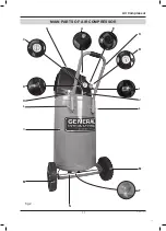
Page 10: ...r pump to the tank K Handle For transportability L Handle Bolts Allows attachment of handle removal for storage M Wheels Allow easy portability N Rubber Foot Provides anti vibration and stability O Air Tank 20 gallons 75 7 liters Further Functional Information TANK SAFETY VALVE The safety valve automatically relieves pressure from the air tank in the event of excessive pressure build up Safety Val...

Page 11: ...11 AC1220 man v 190926 Air Compressor 11 MAIN PARTS OF AIR COMPRESSOR N G A M M K L L B C D E F H I O fig 2 J ...

Page 12: ...on the CFM draw of the tools being operated your new air compressor can be used for operating paint sprayers air tools grease guns airbrushes caulking guns abrasive blasters tire plastic toy inflation spraying weed killer and insecticides etc Proper adjustment of the air pressure regulator is necessary for all of these operations Refer to the air pressure specifications provided with the tool you ...

Page 13: ...n air hose Your air compressor is supplied with a 1 4 push connect air coupler fig 3 With a factory installed air coupler your compressor is ready to accept air hoses equipped with 1 4 male air connectors fig 4 Use only air hoses rated for use with 150 psi air pressure or higher To install any air hose equipped with a 1 4 male connector fig 4 1 Simply push the connector or plug into the fitting an...

Page 14: ... sure it is within the safety standards required to perform the task If using a pneumatic tool the manufacturer should have recommendations in the manual for that particular tool on operating psi settings Drain Valve Make sure the tank drainage valve fig 5 is closed and not in the open position Pressure Switch 1 Check that the red pressure switch button is pushed down to the OFF position fig 6 2 E...

Page 15: ...er follow these tips 1 Try to keep the air compressor stored in temperatures above 32 F 0 C 2 Open the air tank drain valve and release all air pressure from the air tank before attempting to start in cold weather After air is released from air tank close drain valve 3 Pull the ring on the safety valve before each use to make sure the valve is functional 4 Plug the air compressor directly into a 1...

Page 16: ...utomatic reset thermal overload protector which will shut off the motor if it becomes overheated If the thermal overload protector is actuated the motor must be allowed to cool down before start up is possible NOTE To reset the motor overload turn the power switch to the OFF position and unplug the unit from the power outlet Allow 10 minutes minimum for motor overload cut out to cool and reset Uni...

Page 17: ...lve 3 Check valve by pulling on ring If condition persists replace valve Safety valve releases Defective pressure switch Replace pressure switch Pressure in tank falls 1 Air leaks at joints 1 Allow the compressor to build pres sure in the tank to the max pressure if possible Spray or brush soapy water on all air connections and look for bub bles Tighten leaky connections Do not over tighten 2 If t...

Page 18: ...lve dam aged Stop the compressor and contact cus tomer support Compressor doesn t provide as much air as when new and or cuts off after a much shorter time period 1 Tank has reduced capacity due to water retention 2 Pressure switch is out of adjust ment 1 Open drain valve to release water 2 Contact customer support Pump unit does not stop when the tank reaches maxi mum working pressure Defective o...

Page 19: ...19 AC1220 man v 190926 Air Compressor This page intentionally left blank ...

Page 20: ...20 General International ...

Reviews: