Introduction & Specifications
Product Overview
076R174-000
SpectraComm SDT
1-5
Issue 4
Installation and Operation Manual
SC-SDT Front Panel Interface
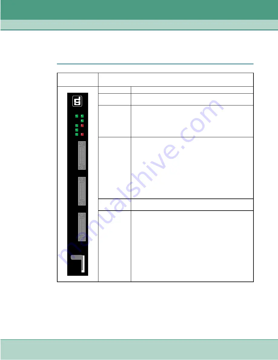
Port LEDs indicate the activity and/or status of the device, the ethernet interface, and of the
individual ports. The table below describes the LED states.
Table 1-1
Front Panel Connectors and Indicators
SC-SDT Front
Panel
Description
ON
Steady GREEN indicates power is supplied to the unit.
INS
Steady GREEN indicates the device is operational and running an
active application.
LAN
Steady GREEN indicates the associated ethernet link is up.
LED OFF indicates the associated ethernet link is down.
Flashing GREEN indicates the associated ethernet link is
receiving/transmitting data.
PORTS 1- 3
Steady GREEN
Port is configured and a transport link between two SC-SDT
devices is established.
Flashing GREEN
Port is configured, a transport link between two SC-SDT devices is
established, and data is passing on the link.
LED OFF
Port is not configured, or
Port is configured but the transport link between two SC-SDT
devices is not established.
TM (Test Mode) Steady RED when unit is performing loopback or diagnostics.
(Future use)
ALM (Alarm)
Steady RED when unit is in a major alarm condition.
(Future use)
PORT 1
INS
PORT1
PORT2
PORT 2
SC SDT
PORT 3
ON
PORT3
AL
TM
ET
Summary of Contents for SpectraComm SDT
Page 73: ......


