3.
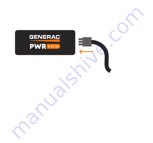
Insert the voltage cable
into the side of PWRview.
4.
Snap PWRview onto
the mounting plate.
Page 1: ...WELCOME GUIDE ...
Page 2: ...d Google Play Open the PWRview Installer App on your phone and follow the instructions to register The PWRview Installer App will help to guide you through the install and confirm the system is working correctly ITEMS NEEDED BEFORE STARTING Smartphone Flashlight Thick insulated rubber gloves Screwdrivers Pliers Two empty breakers or one two pole breaker NOTE The voltage cables on the PWRview Meter...
Page 3: ...rdance with the applicable electrical code for the region in which PWRview is being installed Whenever possible power should be disconnected upstream from the installation location before attempting installation of PWRview If power cannot be disconnected high voltages may still be present and warning must be taken to avoid injury If PWRview is not used as instructed its protection mechanisms may b...
Page 4: ...na and cable Antenna Mounts x2 Current Transformers x2 Voltage Cable PWRview Meter Mounting Plate WHAT S INCLUDED Wire Nut x1 Wiretaps x3 Screws x2 Cable Ties x2 Jumper Wires x3 Generac Sticker ALSO INCLUDED ...
Page 5: ...p 4 Connect the CTs Step 5 Connect the antenna Step 6 Connect the PWRview Step 7 Check your work Step 8 Connect to the PWRview App Step 9 Replace the panel cover Steps to follow If you get stuck at any point visit www generac com service support PWRview for walkthrough videos and helpful tips ...
Page 6: ...nel then remove the cover After opening the panel you should see the wires going into each breaker and main lines from the utility DANGER Electrocution Even with the main breaker in the OFF position the potential for energized wires exists The main utility lines and connections will be exposed and energized ...
Page 7: ...If your panel has a secondary cover that hides the main utility line please remove that as well OFF OFF OFF ...
Page 8: ...g plate to your panel Ensure that there is enough room for the wiring to reach PWRview once it s clipped into place but do NOT clip it into place yet NOTE The self drilling screws will need pressure to drill through the metal You can also drill a pilot hole to make it easier Just be sure you use a 1 8 or smaller drill bit ...
Page 9: ...NOTE Be sure to account for the length of the CTs and the 2 foot voltage cable and ensure that there is enough room on the sides of PWRview for the wires and antenna to connect to ...
Page 10: ...ite wire to the neutral bus bar usually located next to the breaker OFF OFF OFF Black Wire Red Wire White Wire NOTE The blue wire is only needed when connecting a CT to Port 3 which is not used in a 2 phase consumption only installation If the blue wire is not needed twist the wire nut onto the blue wire For more installation types visit www generac com service support PWRview ...
Page 11: ...5A or 20A circuit breaker and replace it with the jumper wire provided in the contents of the box Then take the wiretap and insert the jumper wire the wire from the PWRview and the original wire you removed from the breaker It might take a little force to ensure the wires are secured into the wiretap all the way NOTE To remove a wire from the wiretap simply pull on the wire and twist it ...
Page 12: ...e at the bottom to open the jaws WARNING Do not touch the exposed main line connections to the main breaker as death or serious bodily harm may result NOTE Make sure the label on the CT is facing the utility where the power comes from and not the breaker panel ...
Page 13: ...ower lines Ensure CT1 goes to Phase A the same phase for the black voltage wire CT2 goes to Phase B the same phase for the red voltage wire Pay close attention to the direction that the label on the CT is facing the label should face the utility ...
Page 14: ...use the 3 4 antenna mount If panel is situated outside knock should be on the bottom or through back into wall to prevent water intrusion 2 Once you have found a knockout that is the appropriate size remove the metal to expose the hole Using a screwdriver or gently tapping with a hammer may be needed ...
Page 15: ...3 Thread the extension cable through the antenna knockout mount then screw on the antenna 4 Insert the antenna through the open knockout until the antenna mount clicks into place ...
Page 16: ...Step 6 CONNECT PWRVIEW 1 Connect the antenna extension cable to the side of PWRview 2 Connect the CT s to the appropriate ports on the side of PWRview 2 1 ...
Page 17: ...3 Insert the voltage cable into the side of PWRview 4 Snap PWRview onto the mounting plate ...
Page 18: ...are facing the utility 5 Turn the main breaker to the ON position The next steps will guide you through configuration and confirming the operation of the PWRview meter PWRVIEW PORT PWRVIEW CONNECTION PANEL CONNECTION PANEL POSITION Voltage Connector Black Empty Breaker 1 Phase A Red Empty Breaker 2 Phase B Blue No connection Capped wire nut White Neutral Bus bar NA Port 1 CT1 Utility line Phase A ...
Page 19: ...NOTE You can use the 2 cable ties to clean up your PWRview s wiring OFF OFF OFF 1 2 3 4 ...
Page 20: ...Step 8 CONNECT TO THE PWRVIEW INSTALLER APP Now that the PWRview Meter has been installed use the PWRview Installer App to complete the installation Installer Installer ...
Page 21: ......
Page 22: ...e breaker with PWRview s black wire STATE LED BEHAVIOUR Powered Solid Red WiFi Connected Solid Blue Normal Operation Breathing Blue WiFi Network Lost Slow Flashing Blue 2s 2s Attempting to Join WiFi Network Fast Flashing Blue 0 5s 0 5s Configuration Data Transfer Blinking Purple Firmware Upgrade in Progress Solid Yellow FLASHING LIGHT DEFINITIONS ...
Page 23: ...onfigure PWRview and connect it to your own WiFi network Long beep Voltage warning conditional Indicates that two wires are connected to the same phase For North American apartments this means that one of PWRview s wires should be moved to a different breaker This tone can be ignored for all other 2 phase installations Long chime PWRview joined network successfully PWRview successfully joined your...
Page 24: ...user s body must be maintained at all times Further RF exposure reduction can be achieved if the product can be kept as far as possible from the user s body or set the device to a lower output power if such a function is available Separate approval is required for all other operating configurations including portable configurations with respect to 47 CFR Part 2 1093 and different antenna configura...