8
ADDING A SECOND DISPLAY UNIT TO
THE SYSTEM
A second display unit can be added to an existing system as fol-
lows:
1. Install two non-rechargeable AAA 1.5V batteries into the
second display unit. Observe correct battery polarity which is
indicated within the battery compartment.
2. Follow steps 21A through 24 in the “Installation” section.
NOTE:
Adding a second display unit to an existing system will not
affect the pairing information in the original display unit. The
original display unit will continue to function normally.
APPENDIX
RETROFITTING THE NEXUS REMOTE MONITOR INTO A
PRE-2010 MODEL GENERATOR
The Nexus Remote Monitor was developed for the 2010 Home
Standby product line but is also compatible with several of the
2008 and 2009 Home Standby models.
• It is fully compatible with 2008/09 17 and 20kW models with 3
status LED’s on the side panel.
• It is compatible with 2008/09 10 and 14kW models with 2
status LED’s on the side panel, except the yellow Maintenance
LED on the Nexus Remote Monitor will not function.
• It is not compatible with 2008/09 8kW models.
The 4-wire LED wire harness in pre-2010 models needs to be
separated from the main wire harness to provide enough length to
reach the generator transceiver.
The following instructions replace Step 11 in the general installa-
tion instructions.
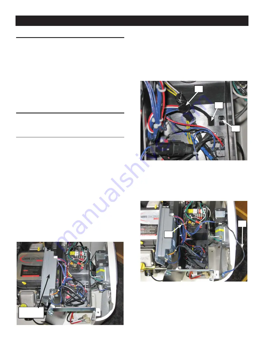
1. Remove the four screws holding the control panel in place.
2. Lift the control panel up and move it out of the way (Figure
1).
Figure 1 — Remove the Control Panel
3. Cut the tie wrap holding the 4-wire LED wire harness to the
enclosure (Figure 2, "A").
4. Carefully cut and remove the tape from the main wire harness.
(Figure 2, "B").
5. Temporarily pull the 4-wire LED wire harness up through the
hole in the control panel (Figure 2, "C").
Figure 2 — 4-wire LED Wire Harness Position
6. Separate the 4-wire LED wire harness from the rest of the
wire harness, cutting and removing all but the last tie wrap
(Figure3, "D") holding the 4-wire LED harness (Figure 3, "E")
to the main harness.
Figure 3 — Separate the 4-wire LED Wire
Harness from Main Harness
7. Route the 4-wire LED wire harness back down through the
hole in the control panel (refer back to Figure 2, "C").
8. Route the 4-wire LED wire harness back to the generator
transceiver, making sure there is enough wire length to plug
into the Generator Transceiver.
9. Replace the control panel and secure with the four mounting
screws.
10. Return to step 12 in the general installation instructions.
Wireless Display System
Move Control
Panel
A
B
C
D
E


