


Maintenance
28
Owner’s Manual for 60 Hz Air-Cooled Generators
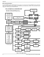
Figure 4-8. Valve Clearance Adjustment (11-22 kW)
6.
Turn the pivot ball stud (D) using a 14 mm wrench
(9 kW units), 8 mm wrench (11 kW units), or 10 mm
Allen wrench (16-22 kW units) while checking
clearance between the rocker arm (E) and the
valve stem (F) with a feeler gauge. Adjust
clearance as per
.
NOTE:
Hold the rocker arm jam nut in place as the pivot
ball stud is turned.
7.
When valve clearance is correct, hold the pivot ball
stud (B) in place with a wrench and tighten the
rocker arm jam nut. Tighten the jam nut according
to the following torque specifications:
8.
After tightening the jam nut, recheck valve
clearance to verify it did not change.
9.
Install new valve cover gasket.
10.
Install the valve cover. Tighten fasteners in a cross
pattern, torquing to:
NOTE:
Start all four screws before tightening, or it will
not be possible to get all the screws in place. Verify the
valve cover gasket is in place.
11.
Install spark plugs and torque to 18 ft-lbs (25 Nm).
12.
Reattach the spark plug wire to the spark plug.
13.
Repeat the process for the other cylinder if
necessary.
Battery Maintenance
The battery should be regularly inspected per the
. Contact an IASD for assistance if
necessary.
Proceed as follows to inspect the battery:
1.
Press the OFF button to shut down the generator,
then lift the lid and remove the front panel.
2.
Remove the 7.5 amp fuse from the control panel.
3.
Remove the intake side panel. (See
.)
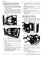
4.
See
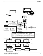
. Disconnect the white battery
charger cable.
5.
See
. Inspect the battery posts and
cables for tightness and corrosion. Tighten and
clean as necessary.
Figure 4-9. Battery Cables
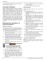
6.
(Unsealed batteries only): Completely disconnect
the battery. Check the battery fluid level and, if
necessary, fill with distilled water only. DO NOT
use tap water. Also, have an IASD or a qualified
service technician check the state of charge and
condition.
7.
When inspection is complete, reconnect the battery
cables, the battery charger cable, reinstall the
intake side panel, and reinstall the 7.5 amp fuse.
8.
Reinstall the front panel and close the generator lid.
9.
Place the controller in AUTO mode.
9 kW
53 in-lbs (6.0 Nm)
11 kW
72 in-lbs (8.2 Nm)
16–22kW
174 in-lbs (19.68 Nm)
9 kW
80 in-lbs (9.0 Nm)
11–22kW
60 in-lbs (6.8 Nm)
002380
C
D
E
F
001832
–
+
(000162)
WARNING
Explosion. Do not dispose of batteries in a fire.
Batteries are explosive. Electrolyte solution can cause
burns and blindness. If electrolyte contacts skin or eyes,
flush with water and seek immediate medical attention.
(000137a)
WARNING


