


Maintenance
Owner’s Manual for 60 Hz Air-Cooled Generators
29
Always recycle batteries in accordance with local laws
and regulations. Contact your local solid waste collection
site or recycling facility to obtain information on local
recycling processes. For more information on battery
recycling, visit the Battery Council International website
at:
http://batterycouncil.org
.
Strictly observe the following precautions when working
on batteries:
•
Remove the 7.5 amp fuse from the generator
control panel.
•
Disconnect the battery charger as directed in
.
•
Remove all jewelry—watches, rings, metal objects,
etc.
•
Use tools with insulated handles.
•
Wear rubber gloves and boots.
•
Do not place tools or metallic objects on top of the
battery.
•
Disconnect the charging source prior to connecting
or disconnecting battery terminals.
•
Wear full eye protection and protective clothing.
•
If electrolyte contacts the skin, wash it off
immediately with water.
•
If electrolyte contacts the eyes, immediately
thoroughly flush with water and seek medical
attention.
•
Wash down spilled electrolyte with an acid
neutralizing agent. A common practice is to use a
solution of 1 lb (454 g) bicarbonate of soda to 1 gal
(3.8 L) of water. Add bicarbonate of soda solution
until the evidence of reaction (foaming) has
ceased. Flush the resulting liquid with water and
dry the area completely.
•
DO NOT smoke when near the battery.
•
DO NOT cause flame or spark in the battery area.
•
Discharge static electricity from the body before
touching the battery by first touching a grounded
metal surface.
Cleaning the Sediment Trap
The sediment trap removes contaminants (moisture and
fine particles) from gaseous fuels before they enter the
fuel regulator. Accumulated moisture and particles must
be emptied from the sediment trap per local codes and
guidelines.
Proceed as follows to clean the sediment trap:
1.
Remove the intake side panel (see
).
2.
Turn the generator fuel supply off.
3.
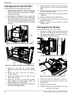
See
. Unscrew and remove the cap (A).
Figure 4-10. Cleaning the Sediment Trap
4.
Use a clean-out tool (not provided) to remove
accumulated moisture and particles from the cap
and body (B).
5.
Wipe the inside of each component with a clean,
dry, lint-free cloth.
6.
Seal the threads of the cap with appropriate
sealing compound. Install the cap and hand-
tighten.
7.
Tighten the cap with an appropriately sized pipe
wrench. DO NOT overtighten.
8.
Turn the generator fuel supply on. Check for leaks
by spraying all connection points with a non-
corrosive gas leak detection fluid. The solution
should not be blown away or form bubbles.
9.
Install the intake side panel.
Attention After Submersion
DO NOT start or operate the generator if it has been
submerged in water. Have an IASD thoroughly clean, dry,
and inspect the generator following any submersion in
water. If the structure (home) has been flooded, it should
be inspected by a certified electrician to verify there won’t
(000164)
WARNING
Electrical shock. Disconnect battery ground
terminal before working on battery or battery
wires. Failure to do so could result in death
or serious injury.
(000138a)
WARNING
WARNING
Environmental Hazard. Always recycle batteries at an
official recycling center in accordance with all local
laws and regulations. Failure to do so could result in
environmental damage, death or serious injury.
(000228)
001821
A
B


