Generac Power Systems 006873 Owners & Installation Manual Download Page 12

Section 3: Installation, Tests and Troubleshooting

8

Owner’s/Installation Manual for SMM

Figure 3-2. Mounting Dimensions

Connections

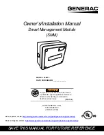
Figure 3-3. Wiring Diagram

1.

Turn OFF both UTILITY (NORMAL) and
EMERGENCY (STANDBY) power supplies before
connecting power source and load lines to transfer
switch and SMM.

NOTE: 

Suitable conduit fittings must be installed in

knockout openings when running supply and load wires.

NOTE: 

Use at least 75 ºC 

(167 ºF) 

rated wire and gauge

per installation instructions. Refer to table for
recommended wire size based on load current.

2.

Run line supply wires per applicable NEC code
articles for wiring method selected.

3.

Run load wires per applicable NEC code articles
for wiring method selected.

4.

Connect line supply wiring to line side of SMM
contactor field terminals. See 

Figure 3-2

. Tighten

field terminals to 25 

in-lbs

 (2.8 Nm).

5.

Connect load supply wiring to load side of SMM
contactor field terminals. See 

Figure 3-2

.

NOTE: 

If neutral and ground wires are included, connect

inside SMM using a listed termination device.

The unit is now ready to configure, apply power, and
perform testing.

Setting Priorities

High priority 240 VAC loads should be set to the highest
priorities so those loads recover first, in the event of
generator overload. 

NOTE: 

The highest priority, and first load to activate is

Priority 1. The last load to activate is Priority 8. 

Setting priority determines timing for 3 scenarios:

Order in which loads recover

Delay time until power returns during an outage

Delay time for post load shed recovery

Height (in/mm)

H1

6.17/156.8

H2

2.36/60

Width (in/mm)

W1

7.06/179.4

W2

4.72/120

Depth (in/mm)

D1

3.7/94

Legend
A

Red (240 VAC - Line)

B

Black (240 VAC - Line)

C

Red (240 VAC - Load)

D

Black (240 VAC - Load)

E

White - Neutral (as required)

F

Green - Ground (as required)

G

Black - Factory (PCB)

H

Red - Factory (PCB)

I

Blue - Factory (PCB)

J

Blue - Factory (Jumper)

W1

W2

H2

H1

D1

000107

000108

A

B

E

F

C

D

I

H

G

J

Temperature rating of conductor: 75 ºC (167 ºF)
Conductor types (must be copper): RHW, THHW, THW, 
THWN, XHHW, USE, ZW

Size AWG

Maximum Current Rating

14

15A

12

20A

10

30A

8

50A*

* 40A for Type NM cable

Electrocution. Turn utility and emergency
power supplies to OFF before connecting 
power source and load lines. Failure to do so 
will result in death or serious injury.


(000116)

DANGER

Summary of Contents for 006873

Page 1: ...in death or serious injury Owner s Installation Manual Smart Management Module SMM SAVE THIS MANUAL FOR FUTURE REFERENCE MODEL 006873 DATE PURCHASED ______________ WWW GENERAC COM 1 888 GENERAC 1 888...

Page 2: ...tains or emits chemicals known to the state of California to cause cancer birth defects and other reproductive harm 000004 WARNING California Proposition 65 Engine exhaust and some of its constituents...

Page 3: ...3 Smart Management Module 3 Smart A C Module Inside Transfer Switch 3 Know Your Smart Management Module and Carton Contents 4 Section 3 Installation Tests and Troubleshooting Electrical Specification...

Page 4: ...Table of Contents iv Owner s Installation Manual for SMM This page intentionally left blank...

Page 5: ...RAC RESERVES THE RIGHT TO MODIFY THIS MANUAL AT ANY TIME Safety Rules The manufacturer cannot anticipate every possible circumstance that might involve a hazard The warnings in this manual and on tags...

Page 6: ...Section 1 Introduction and Safety 2 Owner s Installation Manual for SMM This page intentionally left blank...

Page 7: ...ed in a properly sized system In any combination of modules the recovery times after a loss of utility power or shutdown due to overload are shown in Table 2 1 NOTE For digital thermostats where a 24...

Page 8: ...power See Table 2 2 NOTE Recovery time is based on priority dial settings See Table 2 1 Test Button C Disables contactor output for a specified time LED D Provides module status See Table 2 3 Contacto...

Page 9: ...f Generator Module detected an overload while trying to recover from a shed situation It identified the offending load and disabled operation for 30 minutes to allow other loads to operate This state...

Page 10: ...or after a shed the module will wait another 5minutes plus Priority delay before attempting to enable Note 2 The Checks power source block monitors frequency and will change state Generator or Utility...

Page 11: ...against rain and sleet and is undamaged by the formation of ice on the enclosure 1 Turn OFF both UTILITY NORMAL and EMERGENCY STANDBY power supplies 2 Choose mounting location near electrical panel a...

Page 12: ...ce The unit is now ready to configure apply power and perform testing Setting Priorities High priority 240 VAC loads should be set to the highest priorities so those loads recover first in the event o...

Page 13: ...d priority time elapses each contactor will CLOSE and LED will illuminate and stay ON 7 Once LED stays ON press TEST button and verify load shed occurs 8 Once load shed occurs LED will flash at one se...

Page 14: ...ator while attempting recovery from a shed It is in a 30 minute lockout wait period Wait 30 minutes from lockout for unit to attempt to re apply load Review all loads enabled in household The generato...

Page 15: ......

Page 16: ...c All rights reserved Specifications are subject to change without notice No reproduction allowed in any form without prior written consent from Generac Power Systems Inc Generac Power Systems Inc S45...

Reviews: