


Generac
®
Power Systems, Inc.
5
3.1
FUNCTIONAL TESTS AND
ADJUSTMENTS
Following transfer switch installation and intercon-
nection, inspect the entire installation carefully. A
competent, qualified electrician should inspect it.
The installation should comply strictly with all appli-
cable codes, standards, and regulations. When
absolutely certain the installation is proper and cor-
rect, complete a functional test of the system.
Perform functional tests in the exact order
presented in this manual, or damage to the
switch could be done.
IMPORTANT: Before proceeding with functional
tests, read and make sure you understand all
instructions and information in this section. Also
read the information and instructions of labels and
decals affixed to the switch. Note any options or
accessories that might be installed and review their
operation.
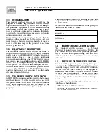
3.2 MANUAL
OPERATION
Do NOT manually transfer under load.
Disconnect transfer switch from all power
sources by approved means, such as a main
circuit breaker(s).
A manual HANDLE is shipped with the transfer
switch. Manual operation must be checked BEFORE
the transfer switch is operated electrically. To check
manual operation, proceed as follows:
1. Turn the generator’s AUTO-OFF-MANUAL switch
to OFF.
2. Turn OFF both UTILITY and EMERGENCY
power supplies to the transfer switch, with what-
ever means provided (such as the main line cir-
cuit breakers).
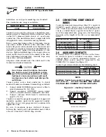
3. Note position of transfer mechanism main con-
tacts by observing display windows in “A” and “B”
in Figure 3.1 on page 6 as follows:
• Window “A” ON, Window “B” OFF - LOAD termi-
nals (T1, T2, T3) are connected to utility termi-
nals (N1, N2, N3).
• Window “A” OFF, Window “B” ON - LOAD termi-
nals (T1, T2, T3) are connected to emergency ter-
minals (E1, E2, E3).
Do not use excessive force when operating
the transfer switch manually or the manual
handle could be damaged.
3.2.1 CLOSE TO NORMAL SOURCE SIDE
Before proceeding, verify the position of the switch by
observing window “A” in Figure 3.1 on page 6. If win-
dow “A” reads “ON”, the contacts are closed in the
normal position, no further action is required. If it
reads “OFF”, proceed with Step 1.
Step 1: With the handle attached to the actuating
shaft, move handle in the direction of the
arrow on the switch cover until it stops — DO
NOT FORCE. Release handle slowly to allow
the spring in the switch box to relax. “ON”
now appears in Window “A” and “OFF”
appears in Window “B”.
3.2.2 CLOSE TO EMERGENCY SOURCE SIDE
Before proceeding, verify the position of the switch by
observing window “B” in Figure 3.1 on page 6. If win-
dow “B” reads “ON”, the contacts are closed in the
EMERGENCY (Standby) position. No further action
is required. If it reads “OFF”, proceed with Step 1.
Step 1: With the handle attached to the actuating
shaft, move the handle in the direction of the
arrow on the switch cover until it stops - DO
NOT FORCE. Release handle slowly to allow
the spring in the switch box to relax. “OFF”
now appears in Window “A” and “ON” appears
in Window “B”.
3.2.3 RETURN TO NORMAL SOURCE SIDE
Manually actuate switch to return Window “A” to the
“ON” position.
3.3
VOLTAGE CHECKS
1. Turn ON the UTILITY power supply to the trans-
fer switch with whatever means provided (such as
the UTILITY maim line circuit breaker).
PROCEED WITH CAUTION. THE TRANSFER
SWITCH IS NOW ELECTRICALLY HOT. CONTACT
WITH LIVE TERMINALS RESULTS IN EXTREMELY
HAZARDOUS AND POSSIBLY FATAL ELECTRI-
CAL SHOCK.
2. With an accurate AC voltmeter, check for correct
voltage.
Single-phase utility supply:
Measure across ATS terminal lugs N1 and N2; N1
to NEUTRAL and N2 to NEUTRAL.
Three-phase utility supply:
Measure across ATS terminal lugs N1 to N2, N2
to N3, and N1 to N3.
Measure across ATS terminal lugs N1 to NEU-
TRAL, N2 to NEUTRAL, and N3 to NEUTRAL.
DANGER
◆
◆
◆
!
!
DANGER
!
Section 3 — Operation
Generac GTS “W” Type Transfer Switch


